
![]()
I have six tube-type TransOceanics, and four of them are H500s. I don't know if that's indicative of how common they are, or whether it was just the breaks. (The other two are an 8G005Y and a B600, both of which work too well for me to fiddle with.)
Tube-type T/Os make nice projects, with a caveat. The advantages are several: they are many so prices aren't crazy (if you shop around); for the same reason you can still find parts or parts-donors for them; they're well documented and not particularly difficult to understand; and when they're working, they work really well. Even this beast below was picking up Radio Australia from a home in Northern California using nothing more than its built-in antennas.
The caveat is that the early models use Loktal tubes, which some people hate; later models use 1-volt miniature tubes, which are easily blown if you accidentally short something to the filament circuit. What makes it particularly painful is that these use the infamous 1L6 pentagrid converter tube. 1L6s are hard to find and expensive (figure $50, where a common tube is in the $5-$10 range). There are a number of ways to work around the 1L6, but the point is, if your 1L6 is bad or missing, you have to do something about it.
One of the best things about the H500 in particular, however, is that there's a Badrestorer's Illustrated Guide to Restoring the Zenith TransOceanic H500 by John Kopp (edited by Ed Morris). It's available as a PDF so you can download it and read it digitally or print it. It's great. It's a lot better than what I'm going to do here.
There are also a number of other websites which deal with Trans-Oceanics, including repair. I'm not going to list them here because they're easy to find using your favorite search engine. Even Bing ought to be able to find something.
I will note this about schematics, however. There are several that I've seen available, and probably more of which I'm not aware. Here are the most notable ones I've come across:
- BAMA has the SAMS Photofact for this unit. SAMS made their own schematics in-house, rather than relying on the manufacturer's data the way Beitman and Rider did.
- Rider has it in the Perpetual Troubleshooter's Manual Volume XXII, beginning P. 22-4. Their schematic has the original 1S4 tube. The dead-tree edition of this volume is expensive (I usually see them for sale north of $100), but if you search you should be able to find a decent scanned copy on the internet for free. Or you can buy a CD-ROM on eBay where someone downloaded the free ones and burned them onto a disc.
- The Internet Archive has some available in different formats (PDF, ePub, Kindle, etc.). Their collection is strange. The first PDF (406.3K) is the full schematic but scanned at a smallish resolution, so it's hard to read at detail level. The second PDF (107.9K) is scanned at a higher resolution and is much easier to read, but it's only the left side. Both "PDF with Text" appear to be the same as the PDF versions. I didn't look at the ePub, Kindle or Daisy versions.
- Nostalgia Air has another so-so quality schematic, this one appears to be Rev C., according to the restoration guide: it has the voltage switch but not the 50A1 tube.
- RadioMuseum has what appear to me to be the same as Nostalgia Air's.
- I've now seen so many different schematics I've lost track of what's what. I have a good "left" and "right" of a Zenith schematic for Rev C., so I put them together into one sheet. This is the one I'm using for this project.
.jpg)
So as I said earlier, I have four of these things (five if you count a half-scrapped-out parts cadaver), and they all need help of some sort. I chose the one in the worst condition to work on first, using the restoration guide I referred to above. By doing the worst first, I figure that when I screw it up, I won't have lost much.
December 13, 2014: Baseline and Initial Disassembly
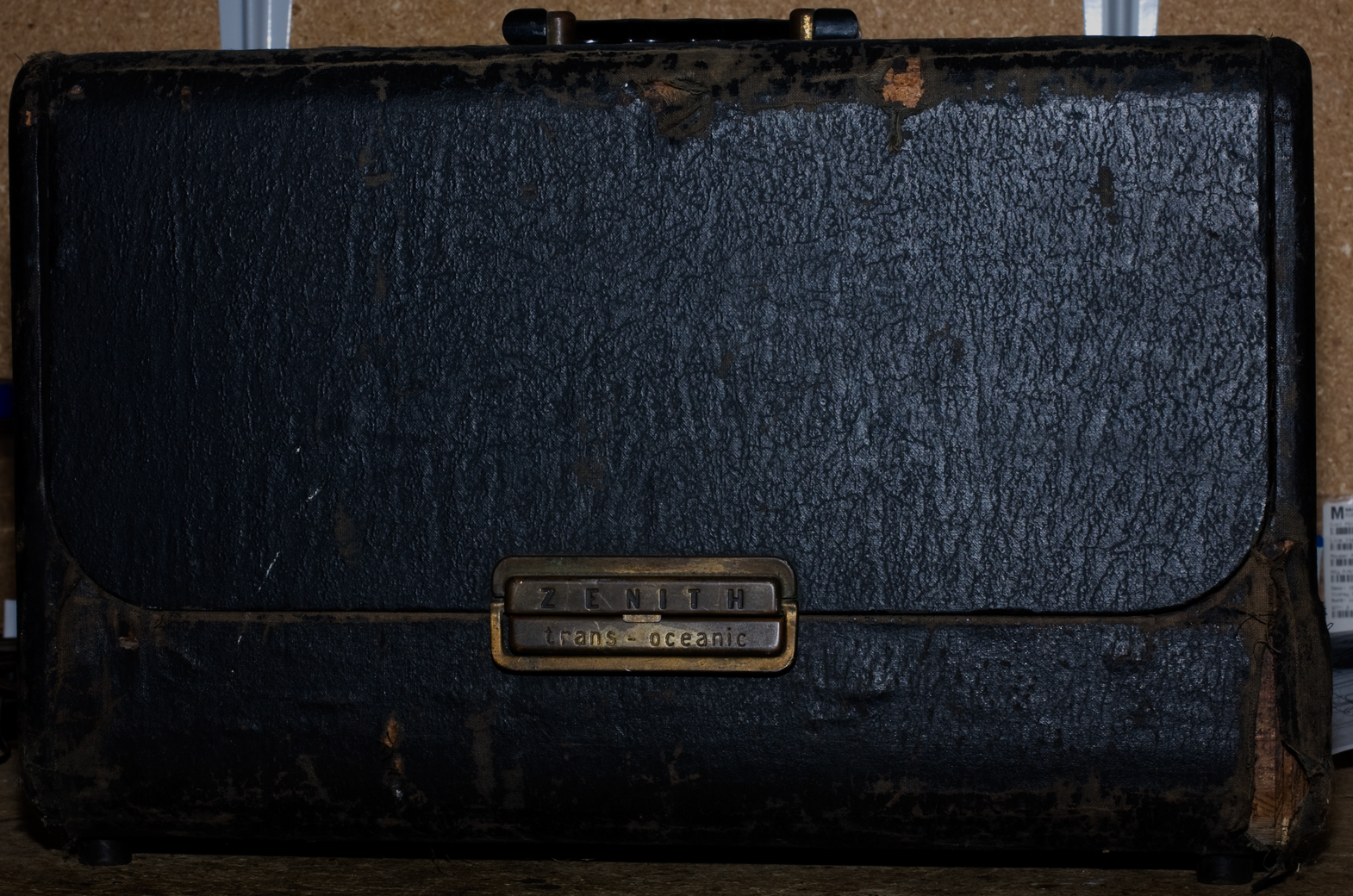
Here's our victim. Cosmetically it's pretty ratty. It was in my sister's house for a few years and I think her cats clawed it, but in fairness it wasn't in great shape when I gave it her. This is likely the most difficult part of the restoration, and the most unlikely to be accomplished.
Photos below. As always, click on any to get a large-size version.


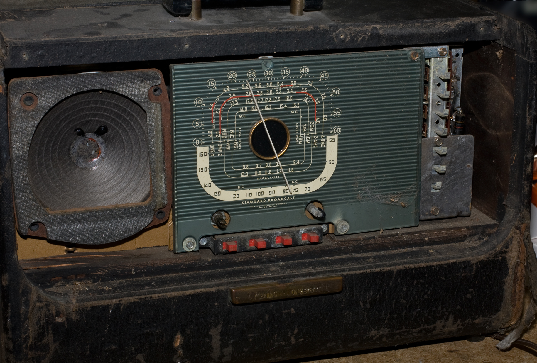
Performance: plays with middling A/C hum on B/C and a couple bands above; dead on the top three with audio that sounds to me like microphonics.
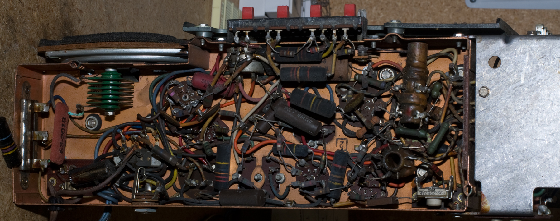
Disassembly was easier than I expected. There are two big chassis screws that hold the chassis to the cabinet, and you get to those through access holes in the bottom of the cabinet; there's a small screw that goes through a metal strap into the top of the cabinet. Pull off the knobs. Undo the two antenna connections (one for the whip and one for the loop). I was having trouble getting the cabinet out so I took the front face panel off (seven slim wood-screws), which pulled the push-buttons off of the selectors. That made the chassis easy to remove. Thank God they didn't mount the speaker directly onto the cabinet, which is what I thought was going to be the case.
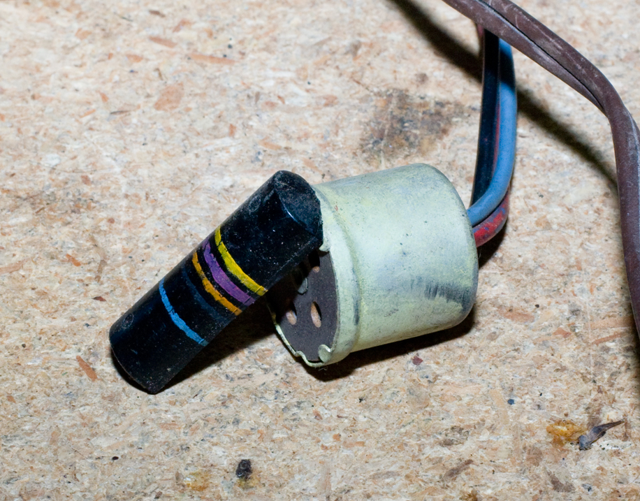
I pulled the chassis out and immediately a half-shell of a big resistor fell out. Not sure where it came from. Think that may have affected the performance?
I also disturbed a garden spider that appeared to be living behind the front panel.
December 14: Tubes / Broken Resistor / Go and Sin No More
All tubes test fine on my Hickok, including the 1L6 which tests strong (for what that's worth).
Page 5 of the Restoration Guide (see introduction for the link) has this box at the bottom outlining chassis variations. Here's a brief version of it:
Baseline: 1S5 tube for Detector/AVC/AF, dual-pin headphone jack.
Rev A: 1U5 replaces the 1S5.
Rev B: earphone jack changed to 1/4-inch phone type.
Rev C: low voltage switch added for AC line voltage less than 110V
Rev D: socket added for optional 50A1 ballast tube
Based on that description, I've got Rev C. The low voltage switch is in the bottom of the chassis and hard to see—it's obviously not meant to be flipped willy nilly. Unfortunately I don't know yet which position it's in.
The broken resistor is another matter. It turns out not to be a resistor, it's C31 (on the Zenith schematic): a 600V .047 uF cap. Woo hoo! I have one.
Soldered it in, decided to try the radio. Top four bands are still dead. A look at the schematic... Nothing where I can really see where something would knock out those bands and not everything else.
After a longer time than I want to admit, I realize that I can do a simple test with my signal generator. It covers the spectrum the T-O can pick up. So I took the whip antenna and hooked it back up. I had to Wavemagnet extension cable from one of my other H500s, and took the 'magnet off it as well, and plugged it in. Turned on the generator, loose-coupled the generator leads next to the antennas, some fiddling—it works!
After that it wasn't "dead" afterall. Some of it was a matter of placing the Wavemagnet or extending the whip and orienting them correctly, but now I at least got atmospherics. The 25M band (2nd one down) turned out to be hot and I was able to pick up some evangelsts. If there's ever a national emergency, find the evangelists' transmitters because they always get through when nothing else will.
So the radio works. Still got an annoying level of hum. Next step will be to try to knock down the hum, then I'll try aligning it. After that I'll see what I can do about the cabinet.
December 16: Alignment
Really, you do the alignment last. But I like to do it early because it gives me a better idea of where I'm at to start with: this radio is a great example.
Besides, I didn't want to start in on the filter condenser.
Another reason this is really a nice project radio: you have to have the chassis out to peak the IF cans, but everything else can (and probably should) be done with the chassis in the cabinet and the antennas hooked up. That said, I did it on the bench anyway, and figure I can touch it up when the chassis is returned to the cabinet later on.
 Zenith says you should put some scrap sheet metal under the cabinet to approximate the affect of theat honkin' big B battery in the cabinet. Since I don't run any of my T/Os on batteries, and I have no interest in doing so in the future, I'm going to skip that step.
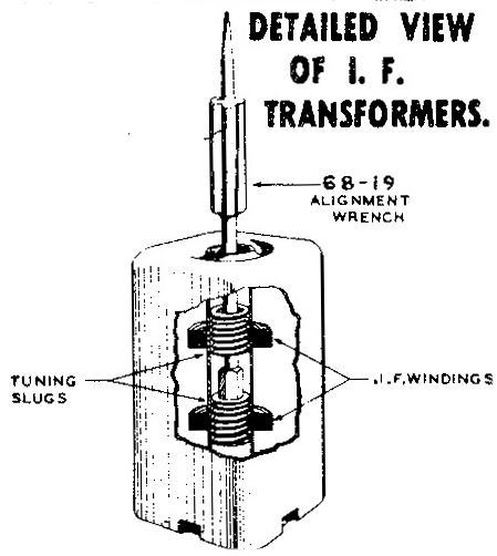
After some initial profanity, because if you aren't swearing during an alignment then you aren't doing it right, I got over my two big hurdles. One was the Zenith single-sided, dual-stage IF can adjustment (for lack of the proper name). Briefly, on most IF cans I've seen, there's a hole in the top and a hole in the bottom. You stick your alignment tool in one side and turn to "peak" the IF, then do the other side; repeat until you can't improve it anymore.
Going in through both the top and bottom of the can is annoying because you either have to have the chassis on its side, or you have to have to stop and turn it over; no matter which you do, it's usually a pain in the ass even with small, simple radios to get to where you can do both sides comfortably. And since the radio is playing while you're doing it, there's always the opportunity for a shock or a short or some other catastrophe.
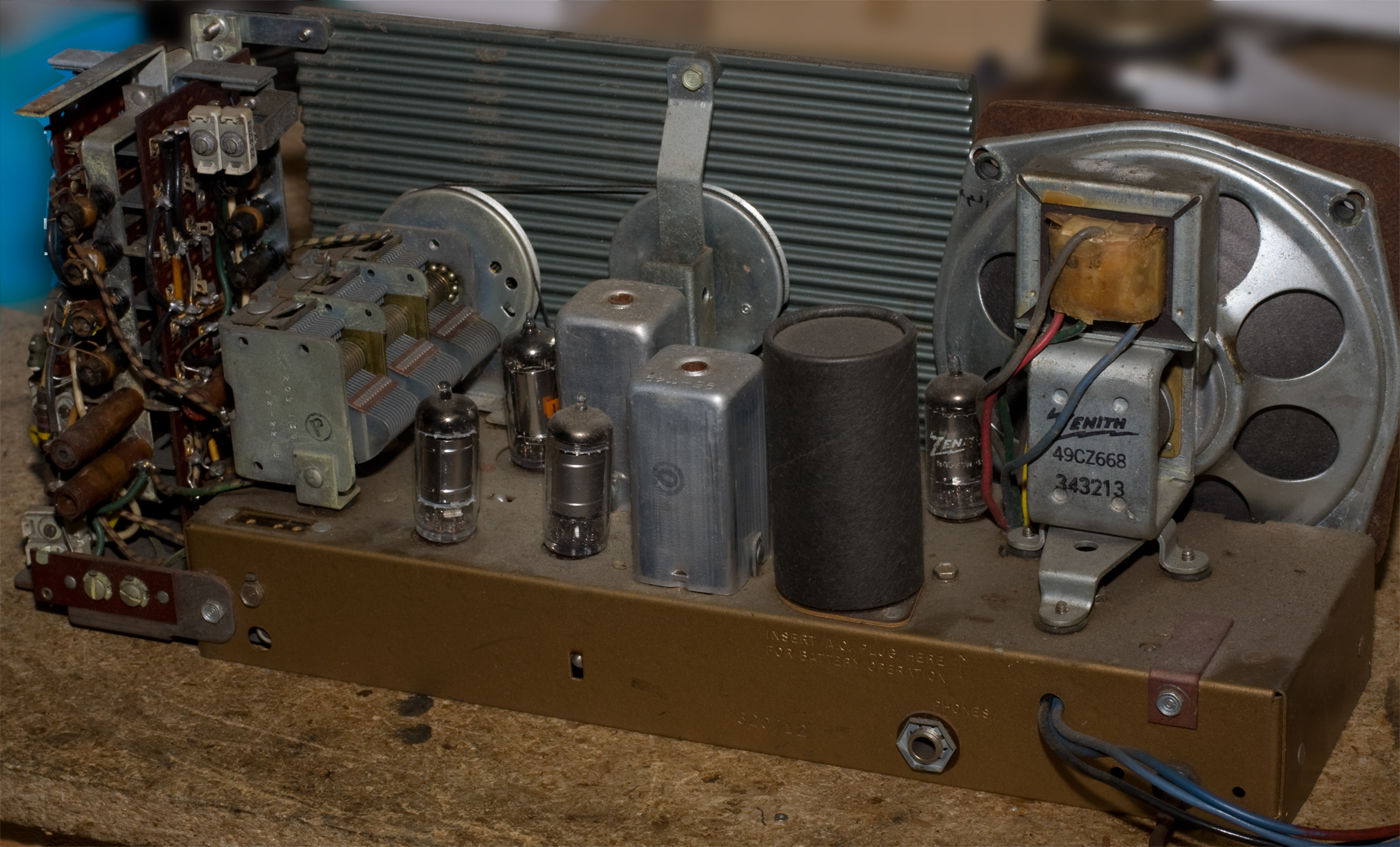
Zenith made these cans that have one access hole on the top, which is great because you just set the chassis upright and leave it be and access all the slugs. Except that instead of having two holes in the top, they have one. One slug has a hollow shaft, so you have to have a tool that can do the top slug, then drop down through it and catch the bottom slug and turn that, too.
I've got a handful of alignment tools of varying, mostly poor, quality (including my home-made bamboo stick whittled from a chinese restaurant chop-stick), so trying to do this was an adventure. Doing the top slugs was pretty easy, but dropping down and getting the lower slugs, and knowing you're doing it, wasn't so obvious. Regardless, I eventually got it. At least I think I did.
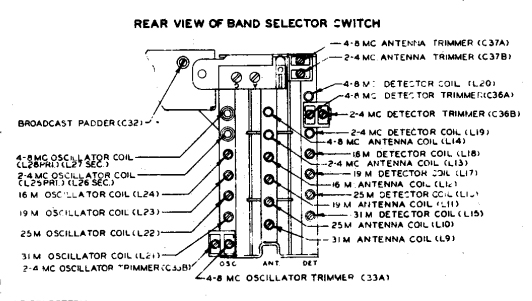 The other hurdle was simply dealing with the alignment instruction diagram, and the simple matter that it's upside down, for reasons I do not understand. If you look at the diagram to the right, see the two screw heads at the top center? There's an upside-down G and A below them? Those are the external antenna and ground connectors. If you flip the graphic 180 degrees, it would oriented the same way it would look with the chassis in its proper, upright position, be it on the bench or in the cabinet.
That may sound trivial and stupid, but if you're trying to figure out which of those twenty-five adjustments you want to put your chop-stick on, having it rotated 180-degrees appears to be one of those brain-games people play to ward off senility. It's very easy to miscount, to swap right and left, and get the wrong one. Guess how I know this?
I managed somehow . Broadcast didn't do a lot but at least two bands on shortwave roared to life as I turned slugs. By the time I was done, and all I've got is the chassis and the extended whip sitting on my garage workbench, I was able to get something intelligible on every band, including the top four that I said were "dead" when I began.
So that's why aligning the radio early in the process isn't necessarily a waste of time.
December 17: Hmm
I hate filter condensers. I hate multi-stage filter condenser cans. The Restoration Guide has a really neat method of restuffing that filter stack; I wish I'd seen it when I attempted the same on my Zenith 6G801Y project. Still, the thought of sawing another one open gives me acid reflux.
I decided that at least I'd see if I could find which stages were bad, and if just tacking a cap on outside might do it. The Old Man had made me a nice capacitor sub-box. There's a rotary switch and caps with about 10 different values, all 600V, plus a button I can use to discharge cans.
So with the set off, I hooked the ground to the Zenith's can pin, which is ground, and used a probe for the other side of the sub box. I turned the radio on. Got hum. Not that horrendous chain-saw, raw AC hum, but a respectable level of hmmmmmmm that needed to be knocked down. For audio I was picking up KFI, a local flame-thrower that's strong enough to get without the antenna connected. KFI's all talk, so I could hear the two drive-time guys yammering about Cuba.
I looked at the can, found one of the pins, put the probe tip on it to add 10 uF, and I saw a little spark and heard a little crack and lost the audio.
Oh great. I figured I blew out all the tubes, including my 1L6. Just great.
Turned the radio off. Waited a moment. Might as well flip it back on and see what happens.
The radio came back on. I could hear KFI. And no hum.
My capacitor sub box was no longer connected to the radio. So I'm not "adding" any capacitance to the filter.
Turned it off. Waited a few. On again. No hum.
Off. On again a few hours later. No hum.
This is what drives me crazy. Some days I think I'm finally getting a little expertise: I can work on old radios without blowing them up; I can solve some basic problems without having to call for help. And then something like this happens, and it's as if I knew nothing more than I did a few years back when I opened up my first GE clock radio; and that everything I do may as well be random.
Small price to pay for no hum, I suppose. But that's it for the day.
December 20: In a Desultory Way
There's a word you don't see in old-radio blogs much.
I've been dragging my feet on continuing with the electrical work. Part of me is lazy; part of me truly subscribes to the "if it ain't broke don't fix it" philosophy, and part of me is worried that if the radio plays fine as it is, that all I'm really doing is inviting disaster. Still—I started this to learn to work on Zenith TOs, and I purposely picked the worst one of the lot so that I could make mistakes without a big loss. I'll press forward.
But mainly I've only been reading the restoration guide and picking at it. I've got a clock oiler, which is a tube of light oil and a six-inch long, hummingbird style tube that allows you to put tiny traces of oil in tight spots; it's great for oiling the bearings on the tuning capacitor. I also picked a couple of easy-access capacitors and replaced them using Kopp's "coil method" of joining new components onto the old wire leads. I was skeptical but I put two caps in and I like it.
I had to stop recapping because a) most of the tubes are bumble-bee style, which means they have colored band markings just like resistors do (which is why I'd originally thought I had a broken resistor when I first started this project). If you've read my other projects, I may have mentioned somewhere that while I'm not color-blind, I'm definitely color weak. Small bits of color, or drab colors, or small bands of drab colors, are really difficult for me to identify. So I'll have to be extra careful in indentifying the caps I want to replace, and that will take time.
And b) I was unhappy to learn that I'm low on high-voltage stuff. I pulled out a 400V .047 uF and replaced it with the only one I had that met the voltage tolerance. A spent a couple of nights sorting through a peanut-butter jar full of assorted capacitors, but they're all low-voltage stuff. I'm going to have to refill my pantry stock.
Taking a break from the chassis, I decided to break the cabinet down some more. I've got the luggage handle removed and the flip-top off. I took the top panel, wiped it down with saddle soap and then went over it with black leather dye. Tomorrow when it's dry I'll go over it with shoe polish and see how it looks.
The top of the cabinet has pulled apart on one side and will have to be glued. I don't have a clamp that wide so I'll either have to get one or maybe stack something heavy on it while the glue dries. Still thinking on that one.
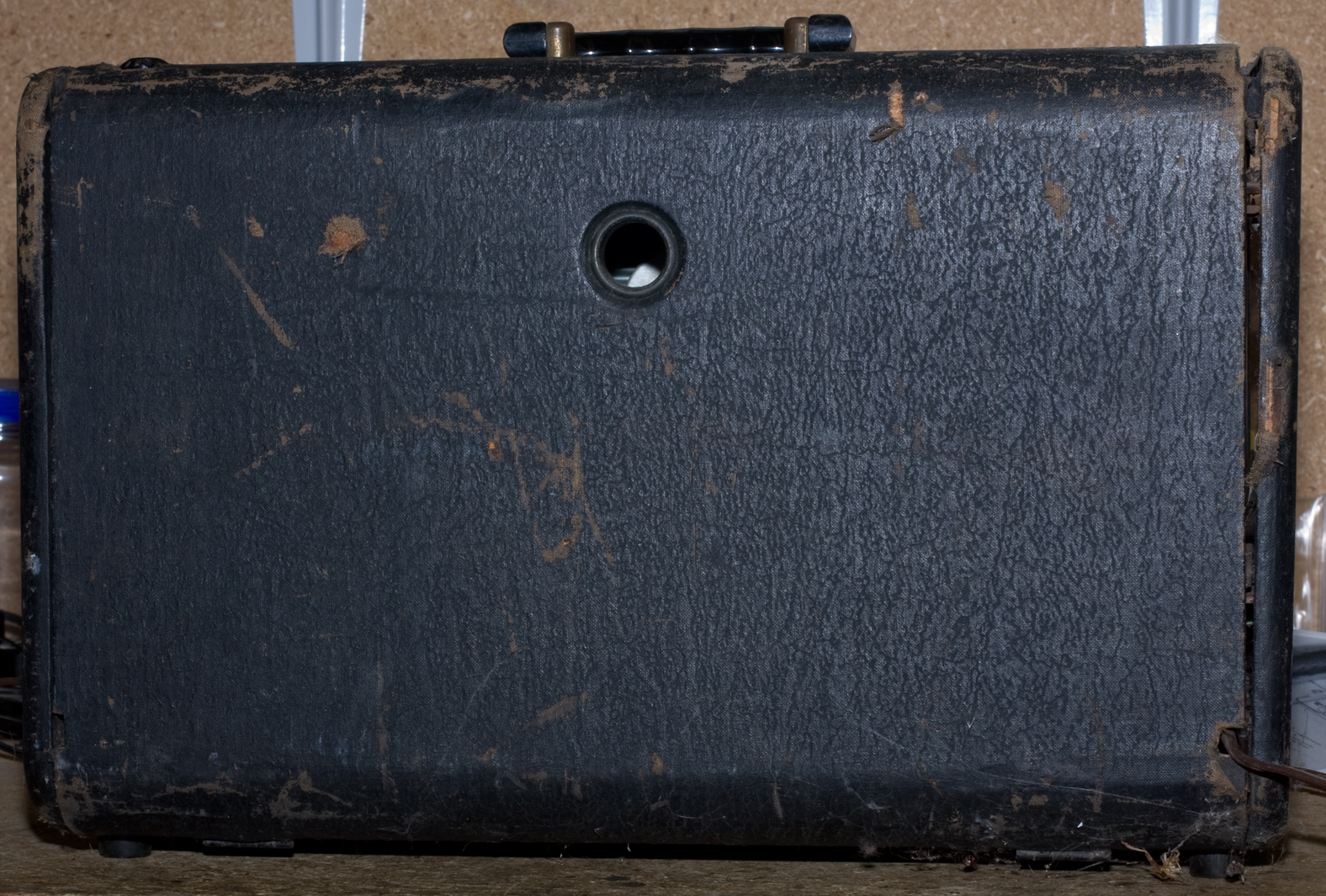
Lastly, I was looking at the suction cups that are on the back panel. They're detachable and are meant to be affixed to the Wavemagnet so you could stick it on a window pane. The classic example (if I can find an illustration) is the T/O sitting in a railroad Pullman car with the Wavemagnet stuck on the window.
The chances that I'll use the suction cups are nil, but I noticed they've gone from the original flexible rubber to something resembling porcelain. I'm tempted to try something from "the Home Shop Machinist" forum. If I try any of these, I'll let you know.
December 21: Last Day Before Christmas
The last day I have to work on this thing before real life interferes.
More fussing with odds and ends. I put shoe polish on the top cover piece and buffed it. Looks pretty good. Unfortunately it was probably the best part of the cabinet even before I touched it. The rest isn't going to clean up as well.
I glued the top tongue and grove where the top of the cabinet had pulled out, set it on its side and set another T/O on top of it—the heaviest thing I could find that was also stable.
Replaced three of the .022 mikes which Zenith sprinkled throughout; two of them on tone controls and one elsewhere. The new caps, as the old ones, seem to make no difference on the tone, or at least so little that I wonder if it's just my imagination that I hear any difference.
Replacing the caps on the tone switches freed up room to get to the 12 mike electrolytic, which is separate from the filter can on the other side of the chassis; I replaced with a 10 uF, which is the closest I've got.
I've been playing the radio every time I swap a cap, figuring that if I screw something up I'll know immediately where the problem likely is. I've also been playing it just to let it play a bit—looking for smoke and waiting for some slower-blowing disaster to strike; so far no problems.
Still no hum.
Just for fun, I took the best of my H500s, the one I was using as ballast on the cabinet being glued, and popped it open to see which version it was. It appears to be identical to the one I'm working on (Rev C). Plugged it in and turned it on and — it's dead. So I guess that one will be next. Either that or I swap chassis.
After that I was letting the old one play (the one I'm working on); plugged in the whip (sorry—the WaveRod) and was scanning the bands to a) verify it was still working everywhere and b) if I could pick up something interesting, and the dial cord broke.
Merry Christmas!
January 2, 2015: Dial Cord
I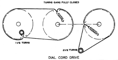 hate dial cords. Even though tubes are obsolete technology, it's still amazing in the way that they work—electricity controlling electricity. Transmission of music, voice and data using electromagnetic waves is incredible. Electromagnetic waves are picked up via a tranducer, amplified, generated, mixed together, filled in, and converted into something we can see, hear or translate into something else that's useful.
But the dial indicator is run by a length of string and some pulleys.
The H500 uses two separate cords and two separate springs (thank God for that), both driven by a wheel attached to the master tuning cap. One string links that drive wheel to a second wheel that turns the dial pointer. The other string links the drive wheel to the axle that turns by the tuning knob in the front. This is the string that broke.
The first string seems to have an easier time of it—the two wheels are the same size and it's a 1:1 drive. But the second string winds around the tuning axle, which is much smaller and there's a big reduction going on: the idea being that you have to turn the tuning knob a lot just to make small changes. That makes precision tuning easier at the expense of rapid tuning. But it also puts a lot more stress on the thread at the tuning axle; plus the cord winds around this axle twice so there's some opportunity for chafing.
The original cord had something interesting—each end had a tiny little metal ring that the wire looped around, and this metal ring was what slipped onto the spring loop. I figure there's no way I can reasonably take the old one off and get the new cord on in its place; my guess is that the metal rings are crimped after threading.
I tried re-stringing this thing at least twice in the last few days but failed each time. Part of the problem is that my garage work area is too cold and I can't pick up anything good on the radio (I find that work generally goes better if I like listening to the radio, and I get frustrated faster if the background noise is irritating). I'm stuck out here because if I bring it into the house, the cats will want to help.
The third time, for who knows what reason, it went on great. I waxed the ends—that helped a bit (previously I'd put a dab of glue on them to reduce fraying). But I don't know, it just went on well and didn't even need rosin. At least not yet.
Started the radio and again it played nicely—no hum.
I finished off by rubbing plastic polish on the handle, and cleaner and a little polish on the plastic face plate (not the dial face). The handle looks a little better but there's not a lot that can be done with it. Likewise the face plate. Awesome (a supermarket spray-bottle cleaning solution) doesn't take the paint off but does clean up oil and dirt nicely; I like it better than Fantastik, 409 and Windex. I put a dab of Meguiar's plastic polish, both "regular" and "clear" on the clear-plastic face and lightly buffed it on the non-lettered area. It looks slightly better but not much. I'll work on this some more later. There are a lot of deep scratches in the plastic and it's unlikely it'll ever look much better than it does right now.
Jan 9: Rubber? I Hardly Knew Her
I've only been dabbing at this (literally and figuratively), so I've only got a lot of bits and pieces today.
the fabric on the cabinet is pretty far gone. There are a couple of completely spots, along with a larger number of deep scuffs and scars. Black leather dye helps but not that much. I tried putting some white glue on to cover a couple of the worst spots, but it doesn't look good. I'll try Badrestorer's JB Weld idea but I'm not expecting much. For some reason I don't understand, I've never had good luck with JB Weld on anything.
Meguiar's plastic polishes did a nice job on the front bezel. There are some deep vertical scratches (possibly hairline cracks) in the clear plastic "glass", that I can't buff out; but the glass itself looks bright and clean now.
I was looking at the dial face and the pointer and theyr'e both lightly covered in a brown patina that I assume is probably tobacco smoke residue. Awesome took it off the dial pointer without hurting the paint, so I tried it on the dial face and it worked there too. I gently wiped the face down, including the painted areas, and it looks a lot better.
I started working on the brass handle mounts with Brasso but they're coming up slow. Badrestorer uses a wire wheel on a Dremel tool, which I don't have. I may pick one up—I have an antique brass door knocker that defies the Brasso & rag method too.
-
The rubber suction cups for the Wavemagnet have hardened into something resembling concrete. A Google search churned up a hundred ideas on what to do, so I'm trying some. I smeared one with Vaseline—nope. Likewise WD-40. Right now I've got one soaking in automatic transmission fluid (type F to be exact) but that not really doing it either.
By coincidence, my HP Laserjet printer's rubber wheel (the one that picks the paper out of the tray) is shot, and while researching that I came across a recommendation for a rubber rejuvinator. I tried the local hardware stores (including the one where competent professionals go) and nobody had it, so I may order one from Amazon.
- I've decided I'm not going to replace the Se diode and revamp the dropping resistors and such. I will check the filament voltages, but if they're good I'm going to leave it alone. So unless I come up with something fantastic to do about the cabinet, I'm going to start putting it back together.
Jan 10: Brass
When I was in Boy Scouts, the new kids would be hazed by being sent out on fools' errands to other campsites looking for left-handed smoke shifters, bacon stretchers, and whatever crap a bunch of teenage boys can think of.
You want real-world fun? Send them out for Rubber Rejuvinator. I've asked for oddball stuff from hardware stores before, but I've never seen such blank looks or outright stumped everyone. It's as if I'd asked for a bottle of mercury vapor to refill my lamps.
Anyway, while I was out I picked up a brass brush for the Dremel, which didn't seem to do anything at all on the handle lugs. But I also picked up the #401 Mandrel and #422 Polishing Cone, and with the #421 polishing compound I already had, and that did the trick. Both lugs buffed up nicely. I went over them again with Brasso and finished off with a touch of Turtle Wax, which I hope might slow oxydization. I also went over the handle with Meguiar's plastic polish and finished with Turtle Wax. Doesn't look pristine but it looks good for its age—like Sophia Loren.
I also got another batch of JB Weld, but I'm waiting for some glue to dry where I'd tacked down loose fabric. If the JB Weld doesn't help, I'm going to start reassembly. I've got other stuff to do and not much work bench space available.
Jan 24: This and That
I haven't said much because I've just been dabbling.
the rubber rejuvinator arrived, and I've been spraying the suction cups. It seems to work but only a little. I can now squeeze the cups and feel a little flexibility, but I've got a cup from another set that's much more flexible, and these are nowhere near that. Additional spraying and soaking doesn't seem to matter. So I figure the rubber rejuvinator may be good for something (rubber belts?) but not for this.
the fabric coverving on the case is just shot. There are big bald spots and it's threadbare in others. No amount of shoe-dye really does it. I bought a can of krinkle-finish black paint and went over it, and that helped tremendously. It's still got bald spots and threadbare spots and it's never going to be great, but it looks a lot better than it did.
the part I glued broke again as soon as I picked up the cabinet, so I picked it apart, cleaned it more thoroughly and glued it again. As soon as that's set, reassembly begins.
Jan 25: Back Together Again
Put it back together with a minimum of fuss and no new breakage, which makes it a triumph at this house. The cabinet doesn't look great, or even good, but it looks fair and that's better than it did when I started. And it plays nice. Plus somehow, unintentionally, the push-button band selectors are working much better.
This project is done.
Now I've got another H500 with a nice looking cabinet that doesn't play, so that'll be next (among my H500s). But I'm going to work on a couple of other projects first.
Current status: runs fine.