
![]()
If you want more of the background on why I'm doing this, check out the beginning of the National NC-173 Project. Otherwise, here's the Cliffs Notes version of it:
I wanted to learn how to repair old tube radios. I bought a boat anchor (the National) but that was really too big a job. My father (a retired electronics tech) suggested I find an old "All-American 5" radio because they were relatively simple, easy to work on, and a good place to begin (unlike getting a portable with 1-volt tubes, which are easy to blow if you make a mistake).
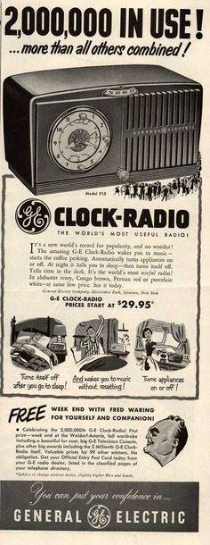
It was harder than I originally thought, but I finally found a radio that fit my criteria: an All-American 5, complete (I didn't want to lay out a lot of money hunting down hard-to-impossible-to-find parts), affordable (I'm shocked what people want for ho-hum table radios, even when they don't work), dead or ailing, and not ugly. I ended up with this nice GE 515F clock radio, which fit the bill in all respects.
In Renovation Realities form, here are the particulars:
- Project: GE 515F
- Budget: $50 (including original purchase price)
- Timeframe: end of June, 2011
 |
Rider manual - from Nostalgia Air (see Sources below) |
In case you care, I thought the following to be useful or interesting:
- Radiomuseum - that's it all right.
- Nostalgia Air - great source for old service docs (under Resources, then by manufacturer, then by model #)
- Antique Radios Forum - tons of stuff, this link goes to a thread on cleaning bakelite cabinets
- Tube Depot - retailer of vacuum tubes at decent prices
Click on any of the photos to see them in a larger size.
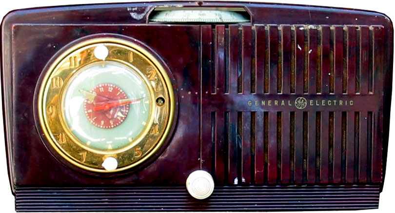 It arrived on my doorstep this afternoon. It's pretty much complete; the bakelight cabinet needs a deep cleaning; there's bad spot I might be able to hide but there's also a big crack I'll just have to live with. It's missing one of the knobs for the clock; I'll have to keep my eye out and see if I can find something that looks enough like it to pass (or better yet, three).
I pulled off the cardboard back, which forms the loop antenna, and looked inside. It appears complete, albiet dusty.
Plugged it in (radio switch OFF) just to see if the clock works. Nope.
Work begins tomorrow.
Cost: Radio - $2 plus about $15 S&H; Caps and resistors: around $7.50
Running Total: $24.50
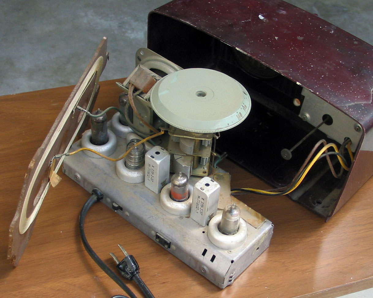 It opened up easily: the back is on with two screws and it holds the loop antenna; the antenna connects with two wires with push connectors, so they came off easily.
Unfortunately, the clock is hard-wired into the chassis, so if you want to fully remove the radio chassis from the clock, you have to unsoldier three wires: two on a switch, and a third on what turns out to be Pin 8 of the 50C5 tube. I think it would be better if the clock wires went to a 3-pin plug. I may do that when I'm putting it back together.
 So here we are—the unit's dead. The AC plug and wire are good, so the problem is somewhere else.
Somewhere on the internet I saw where a guy was working on a chassis and he cut out a piece of cardboard to cover the speaker, so I did the same. Putting a thumb through the speaker by accident is exactly something I would do.
First I checked the tubes, because that's the easiest thing to do. I'd borrowed a tube tester from a friend, a Sylvania Model 140; I love vintage equipment, and reeks with that funky old-electronics smell. But I found out that some vintage gear is too vintage: two of the tubes in my radio are not on the Sylvania's tube scroll, so they'll have to wait. Two tested fine. A third one looks iffy on the Shorts test, but the tube tester's rotary switch is dirty and I'm not convinced it's shorting. But I'm not convinced it's good, either. I may buy another one just to see.
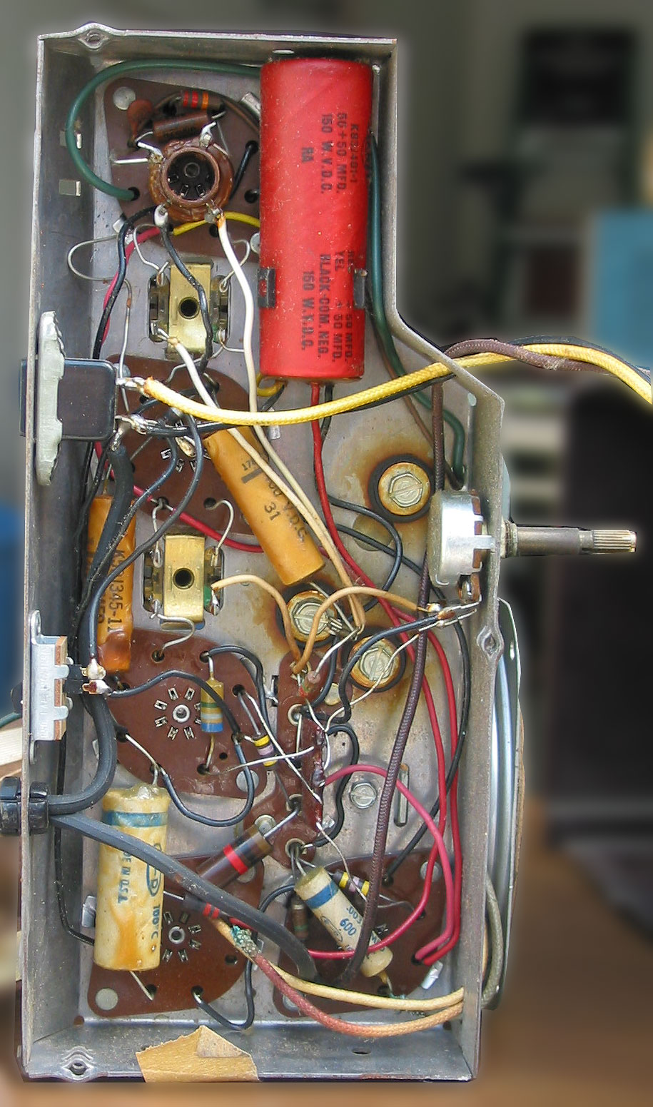
Turns out there are only three old paper caps to replace, so I went ahead and did it.
And now this is where the wheels fall off. I have no idea what the problem is. Since the problem is power (and its lack), I thought I'd trace the power. Okay, except that it doesn't seem to match the schematic. Long story short—nothing got done and I called it a night.
Enough time has passed that I can make jokes about it. At the time I didn't find this amusing at all.
Saturday
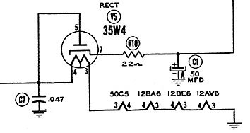
Long story short, after much dicking around, I realized that one end of the AC cord goes to a plug socket (where you can plug in a coffee pot (or something else you want to be turned on by the GE's clock)) and a switch. The other side of the cord goes to pin 8 on the 50C5 tube. Wait—there is no pin 8—it's a 7-pin tube. But for everything I can see, it's on pin 8 of the socket.
Turns out that unused pins on tube sockets make convenient tie points. Problem here is that there's nothing else connected, so I've got an old fashioned open circuit.
But there was something else on pin 8—it was one of the wires going to the clock. I had thought the clock would be wired in-parallel to the radio, but it's wired in-series. So no clock, no power.
I looked all over to figure out where I should put AC wire to complete the circuit, and it crystalizes that I just have no clue about AC circuits. This explains a lot of other problems I have—I can (to some extent) trace a DC circuit, but AC gives me fits.
In the meantime, the easiest thing would be to put the clock back in, as that would complete the circuit. Except the radio was dead when I got it. Maybe the clock is dead. If the clock is dead, that would explain why the radio won't run.
I have an AC cord with a plug on one end and alligator clips on the other, so I hook this thing up to what I think is the clock motor. Plug it in. Nothing. Well, I could be wrong. Hook it up to these two wires. Nothing. How about these two wires? Nothing. How about these two? Nothing.
"Hey, did you know the lights went off in the living room?"
Sigh If you don't pop the circuit breaker, you're not really trying.
It was about this time I decided to call it a day.
Sunday
A consultation with my father (the retired tech), who clarifies the tie-point issue, is also surprised that the clock runs in series with the radio (he suspects someone may have rewired it) and makes some notes on the schematic and emails it back to me. He suggests I tie the AC line from Pin 8 to the B- bus, which I can find by following the black wire from the big 50-mike capacitor.
It's bump day for the Indy 500 so I spend much of the day watching that, and decided to try my hand at destroying the cabinet while I watch. I'd gotten the clock out of the cabinet so now I'm left with a plastic shell. When I first got it, I'd thought it was bakelite and was unhappy to see various comments on the web about how difficult/impossible it is to restore bakelite. But it turns out that isn't bakelite, it's styrene, which is lighter, has some flex to it, and not such a problem.
The thing looks like it was splattered with paint. I don't know what it is, but the upside is that if I put some water on it and let it sit a minute, I can pick these things off with my fingernail. So the afternoon is spent washing/picking/wiping down the cabinet until it's clean. I'll have to get some plastic polish and see if I can buff it up. There's a nasty crack in the top that I can't do anything about, so like any other irreperable scar, it's "character."
Bump day over, I went back out to fire up the radio. I'd forgotten the advice about the B- bus, and instead I'm looking over the schematic, and because I'm an AC idiot and I don't really comprehend the notes, I decide to run the power off the other side of the 35W4 heater. Hook it up. Plug it in. Light!!! Hooray!
zzzzz
tink
God really does look after fools, because it's a $5 tube, not a $50 one, so I ordered one from TubeDepot. Debated about whether to order a couple of spares, especially for the one the Sylvania said may (or may not) be shorted, but decided to err on the side of not spending money. The dead tube went into my dead tube box so I can remember the dumb stuff I've done. And the day is over.
I sufficiently recovered Sunday evening and ordered a Photofact, just to see if it's any better or helpful than the Rider manual. It's not an instant download—I have to wait for the guy to send me a link, so I'll probably get it tomorrow.
Monday
I reclaimed an ounce of self-respect. On the radio chassis, I ran a wire from Pin 8 (the AC line) to the B- bus where the black wire from the big cap hooks up. I have no rectifier tube so I'll have to wait for the mail to try it out.
In the meantime, I bought a pig-tail, one of those short extension cords that are used to connect fat wall-warts to power strips or other sockets that are too narrow to accommodate them. I cut open a wire on the pig-tail, soldered in a fuse holder and electrical-taped it back up. Now I can put in small fuses and try things out without blowing the house circuit breaker. (My father's idea.) It works! I'm able to verify that the clock isn't running even with power across it.
Cost: 35W4 tube: $10 (incl. S&H); Photofact download $5.
Running Total: $39.50
 I don't have the book or I'd quote this properly. There's a guy named Roger Welsch who writes (among other things) books on tractor repair. I have no desire to own a tractor but I love the books and they're entertaining as hell. In one of them (I don't recall which), he says that half the job is the standing around and just looking at it part.
I've been taking the downtime while waiting for the tube to pore over the schematics and whatever else I blunder into. Finally spoke to my father, who between what he was saying and some other things I was reading, I finally started to straighten things out in my mind. I thought.
I keep thinking of the circuit as a series. It's really two circuits in parallel (not counting the clock). One branch runs the five heaters and it's AC; and a parallel branch runs everything else, and the first thing in line is the rectum-fryer (as the old man likes to call it), so that side is DC.
I spent a fair amount of time drawing and redrawing bits, trying to trace the paths. The Rider is confusing me because there are so many intersections and the dot connections are small; I'm continually making mistakes on where things connect and where they don't. The Photofact is a bit less convoluted. But the Rider has socket pinouts and a layout of the chassis, and that's useful. So it's a mish-mosh.
I'm continually trying to convince myself that I'm just starting out. I'm a middle-aged man and I'm learning a new thing almost completely from scratch, something I haven't done since I was in college during the Reagan administration. I'm not used to dealing with these learning curves, and being so far down the bottom of the hill.
The tube arrived so I'm ready. A final conference with my father, who shows me (over the phone) that I've still got the power wired wrong. We finally agree to move the wire I ran from the tie point on P8 of the 50C5 to the B- bus, and instead run it from P8 to the accessory plug socket. The power needs to run across that socket anyway, and there's that switch. It's fine. I say it won't let the clock work—but the clock isn't in the cabinet and doesn't work anyway—we'll cross that bridge when we come to it.
So I resolder the wire. (If you asked me why I didn't just relocate the AC wire from P8 over to the socket—I would have but it wouldn't quite reach). Now I'm ready.
My father had suggested that I check the resistance between the cathode of the rectifier (the new 35W4) and B-. The caps will charge and then it should give me 5~10kΩ or more. Okay. I fire up my VTVM, a Hewlett-Packard 510B, obsessively zero the needle across the scale just because I'm stalling, and then try it. 6kΩ. Should be okay.
I plug it in through the fused extension cord I made the other night.
It starts making noise. I must have the volume pot all the way up because it's loud—
*SNAP*
Oh FUDGE!* Not again!!!
That's the local circuit breaker on the power out I'm using. I'm in the garage next to the washer, and it's the kind they put in bathrooms these days. So at least I didn't blow the house circuit. But still. And why didn't my extension cord fuse blow??
I called my father again in abject failure. He was also surprised. "Did you have anything else connected?"
No. Just the VTVM. I'd left the common connected to B- because I was going to take voltage readings off the plates if/when the radio came up.
The old man suspects that there's a "sneak circuit" somewhere. He said some Hickoks used to have that problem.
Lovely. So I packed up the VTVM and pulled out the Harbor Freight digital. A couple of tests and we should be okay. Try it again.
This time it fires up. I hear that between-station static. Holy s—, it works. The power problem was the problem.
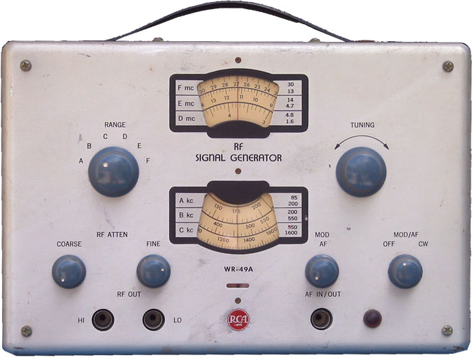 I'm almost disappointed, but then realize I can still muck around with aligning it. So away goes the soldering iron and out comes my RCA signal generator.
I start setting it up. This goes here and this goes—
—and the lead comes off in my hand.
I'm going to have to fix this thing too.
I have to remind myself that this is what I get for buying stuff on eBay, and I knew the risks when I took it. But damn, this couldn't have happened the other night when I was checking it out?
And don't think it hadn't occurred to me that the old man's treasured Hickok signal generator crapped out when we were trying to troubleshoot the National.
I expect the soldering pencil to burn up next.
-----------
* - Only I didn't say "Fudge." I said the word, the big one, the queen-mother of dirty words, the "F-dash-dash-dash" word!
I ended yesterday's post at a good stopping point. In reality I went back a couple hours later to fix the signal generator's output cable, which just needed some soldering and new wrapping with electrical tape. This obviously isn't the first time it's been done. The last person used shrink-wrap on top of everything, and I'd do the same but don't have any that size. I'll pick some up next time I'm at Fry's.
So then it's a matter of hooking everything up for alignment. The alignment instructions on the Photofact say that if I don't have an isolation transformer (I don't), to run a 0.5µF cap betwen the low side of the generator and B-, and a dummy antenna capacitor to the tuning cap, and the meter should hook up across the speaker.
I'm not really set up for this, so very soon I have about 18 alligator clip-wires connecting everything in sight. And it's about this time I start getting shocked. Not zapped, but I'm definitely getting more juice than I was earlier and it's not pleasant.
I remembered reading a discussion of AA5s and two-prong electrical plugs—this sort of thing happens if they're in backward. I pulled the plug and flipped it 180°. Well whaddya know. Either the cord on this thing was never polarized or someone had ground off the wide parts of the blade. Added a polarized AC plug to the shopping list.
Meanwhile, I didn't like the way things were hooked up hither and yon, clips were falling off every time I turned my head, and looked like a bird's nest and asking for trouble. Plus I was confused on exactly where I should be hooked up and what should be tuned; I had no patience reading the Photofact and called it a day.
Next day (truly the 28th), I picked up a two-prong extension cord with a polarized plug at the hardware store, cut the end off, and replaced the old cord. As I'd mentioned ad nauseum above, the old cord was wired one-side to the accessory AC plug and the other to unused Pin 8 on the output tube, and I'd run a wire from P8 back over to the other side of the accessory plug. So screw that—I just wired the AC cord across the AC plug.
Fired it up. Noise. Now what? I'd knocked one of the capacitors loose (one that I'd put in when I recapped it at the beginning of this project). Tacked that back into place. Turned it back on. It works! No shocks!
Decided not to push my luck and left alignment for another day.
Cost: Two-prong AC cord: $1.50.
Running Total: $41.00
 May 30, 2011: More or Less Done
 After a lot more dicking around with alignment, I decided I was done. I'm at beyond the limit of what I know, and I'm just poking around blindly now, which isn't doing me any good. I've been reading procedures on alignment, watching them on YouTube,
and no two methods are the same and none of them completely jibe up with what I'm seeing in the service docs I've got (and they're both somewhat different), and all of this is at odds with advice from my father over the telephone. That and I'm also fighting my equipment: the signal generator is off a little—is it close enough or not? The VTVM is back online but not telling me what I think it should, so is it wrong or (likely) that I'm not used to it and don't have it set up right? I'll have to figure out some experiments for it. Tried to hook up the scope and that didn't do me any good either. Various and sundry other things are giving me similar results. So that's it, I'm done. The radio plays fine as it is, so I'll haul it up with me on my next visit and get some personal tutoring on alignment. And in the meantime, I'll keep an eye out for another dead radio, and I'll have something new to complain about.
So the summary: it's not bad. I wasn't able to clean up the case as well as I thought, but it's better than when I got it. I couldn't align the radio, but I got it to play. The clock doesn't work but I had no expectations about doing anything with that. So all things considered, I'd grade it a "C".
Forgot that I still need the little knobs for the clock...
Visiting my father, so I handed the Telechron clock part off to him. As with everything on this project, it was like pushing a car with the hand-brake set. He identified the bad electric motor after 1 minute (literally) of poking at it, and I think it took 10 minutes to find a replacement in his junk box. It then took approximately 3 hours over two (maybe three) settings to get the clock back together so that it worked properly. Then we rewired it back in so that it would do what it was designed to do: operate as a clock-radio and timed coffee-pot switch.
Then the radio went south again. This turned out to be my solder joints from recapping the radio way back when, which were too small (the joints) and brittle for their own good. So some resoldering, then some lessons on alignment. And it's done, whether it likes it or not.
Ideally the tuner knob should be properly painted, but I have no clue to how to go about it, and less patience for it. So poke this with a fork.