
![]()
I'm not going to go through the big production here as I did with the General Electric. I'm just going to hit the major points and summarize it.
After spending several days with my dad going over a batch of junk radios I'd bought, I felt more confident trying another project on my own. So I picked up this Bendix 753M on eBay for $25 (including shipping). (July 30, 2011)
As usual, you can find the schematic for this radio from Nostalgia Air. They have the Rider version. It appears in Rider's Perpetual Troubleshooter, Volume 23, Page 23-1. It's also in Beitman's Most Needed Radio Diagrams, Volume 14 (1954), Page 18. If you have a choice, Rider has four pages and more info. The Beitman just has the schematic and the dial cord diagrams. I haven't seen the Sams Photofact for this unit so I can't comment on it.
 Those schematics are actually for the model 735M. Mine's a 735MX. I have yet to determine what the difference is. The Rider manual says the final letter indicates the cabinet wood: "F" is Cherry, "W" is blond oak and "M" is Mahogany. My guess is that MX is another variation of Mahogany. The cabinet has a schematic diagram glued to it on the bottom; mine is dry and beginning to disintegrate; I've looked it over and it appears identical to the 735M in the Rider/Beitman manuals.
This one's like my GE project in a variety of ways. As the saying goes, if you fall off a horse, you shoot it, send it to the glue factory, and get another horse, or something like that. Both of these are clock-radios, but whereas the GE's Telechron clock was bad and the radio worked, this supposedly had a working clock but the radio was dead. Both are AA5s, and I wanted to take another stab at one, plus I can get tubes fairly easily and inexpensively if I need them.
I don't know much about Bendix Radio. From what little I've been able to skim off the net, it appears that they were mostly military. They dipped their toe into the consumer market in the early-mid 50s with some radios and televisions, didn't like the temperature and got out.
This particular model shows up in the "Beitman Most Often Used Radio Diagrams" (i.e. schematics and service docs) book for 1955, so I date it such and it seems right for the period. We're moving out of the date Art Deco period and into modernism. It's got a nice wood cabinet, not wood-grain-painted plastic, and it's in good condition so I try out my tyro refinishing skills without having to jump into the deep end. The clock is by Sessions (the GE had a Telechron).
As I mentioned earlier, 753 is the base model, with three cabinet trim versions: "F" is called "The Cascade." "W" is "The Bedford." Mine is a "Marion." Mahogony is my favorite wood (cherry is second), so I was doubly pleased—at least until I looked at the parts price list in the Rider manual, and found out that the mahogony cabinet was the least-expensive of the three. The original buyer of this radio may simply have been cheap.
An interesting adjunct to this: at the time, there were three main sources for service docs: Howard W. Sams, which made Photofacts, Beitman, which made the "Most Often Used Radio Diagrams" books, and John Francis Rider, who published The Perpetual Troubleshooters Manual. Sams made their manuals in-house; Beitman and Rider appear to be using the original manufacturer's docs (at least when available). Also interesting (to me, anyway)—I've got both Beitman's and Rider's docs for this radio. Rider's is a 4-pager, including the schematic, alignment procedures, call-outs, and a parts list with pricing. Beitman condensed this to a single page with the schematic, dial-cord diagram, and the little else they could jam onto a single page. Both Beitman's and Rider's info appear to be from the same source, which I presume is Bendix.
Tube Compliment
12BE6 - Converter
12BA6 - IF
12AT6 - 2nd Detector
50C5 - Audio Out
35W4 - Rectifier
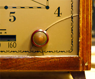
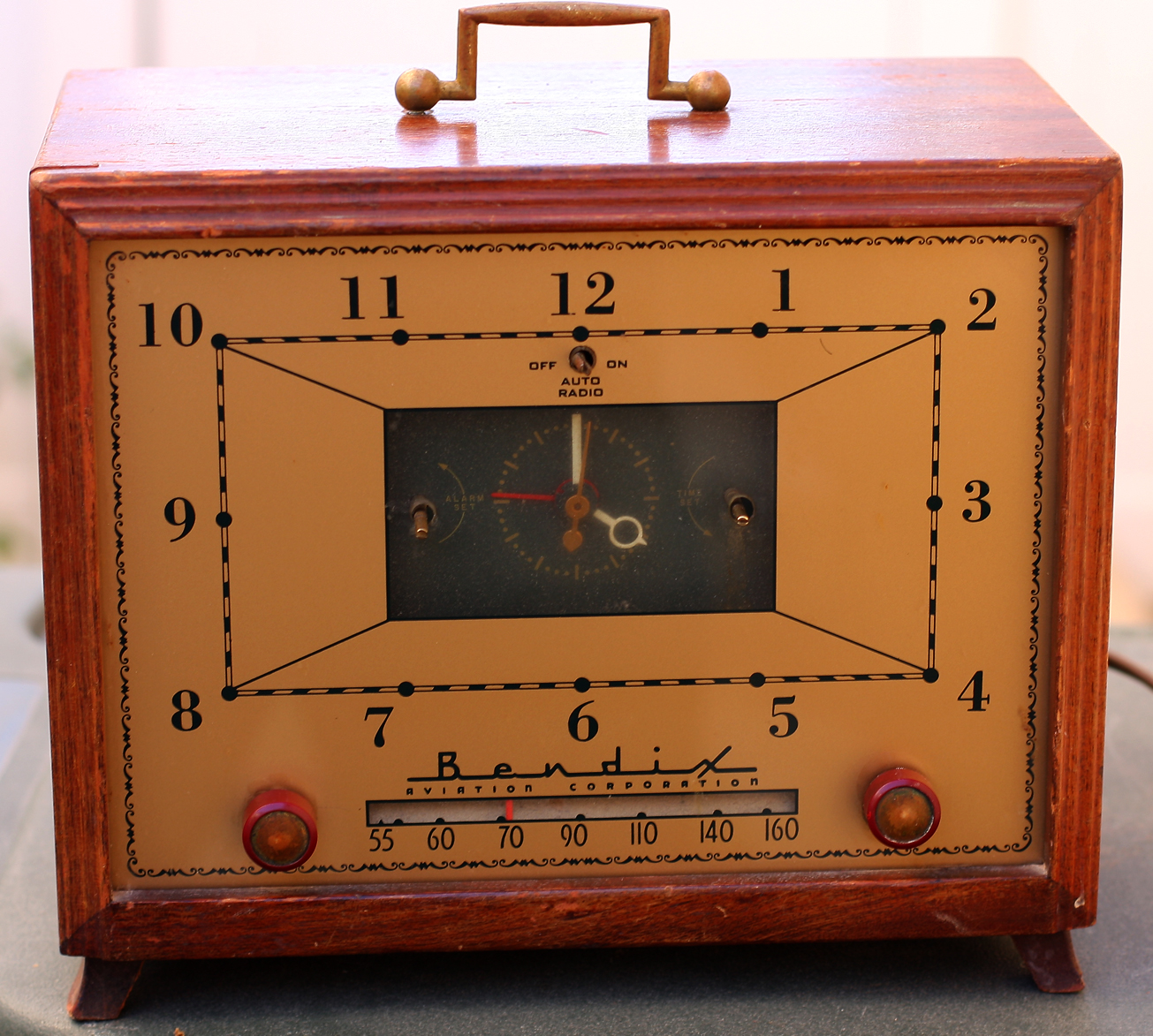 It'd arrived a couple days earlier and I photographed it, but this is the first chance I really had to try to disassemble it. The condition is good. It's missing a couple of the clock-radio knobs on the front, and it seems like it has half the screws and those that are left are all loose. The cabinet is wood and it looks good. The front is entirely glass, no big gouges, scatches, cracks, etc. Could use some cleaning. The window in the middle for the clock seems murky.
Disassembly fairly easy. Three screws (well, the two that were left) on the bottom of the cabinet hold the chassis in. Two screws (out of four, and a corner is broken so it's really down to one) hold the cardboard back & loop antenna on.
This is where it gets complicated. The wires from the chassis to the antenna are directly soldered, so I either have to take them loose or leave it all intact, which will be awkward. So they come off. The wires that go to the speaker, which is screwed (again two out of four, and loose) to the cabinet, are also soldered directly on, so I either have to unsolder them or remove the speaker. I went with the latter, and put a piece of cardboard in front of the speaker cone and rubber-banded it in place.
Now the clock. Again, the three wires are soldered directly into the chassis so I either have to undo them or pull the clock out too. I decided to undo the wires at the chassis.
When it comes time to put this back together, I may replace some of these things with plugs (especially the clock).
Some trouble getting the chassis out, which turns out to be a problem with the cabinet. Internally, up front, the wood has warped and risen up to grab the chassis, so what would normally just pull out now has to be lifted and twisted and worried out.
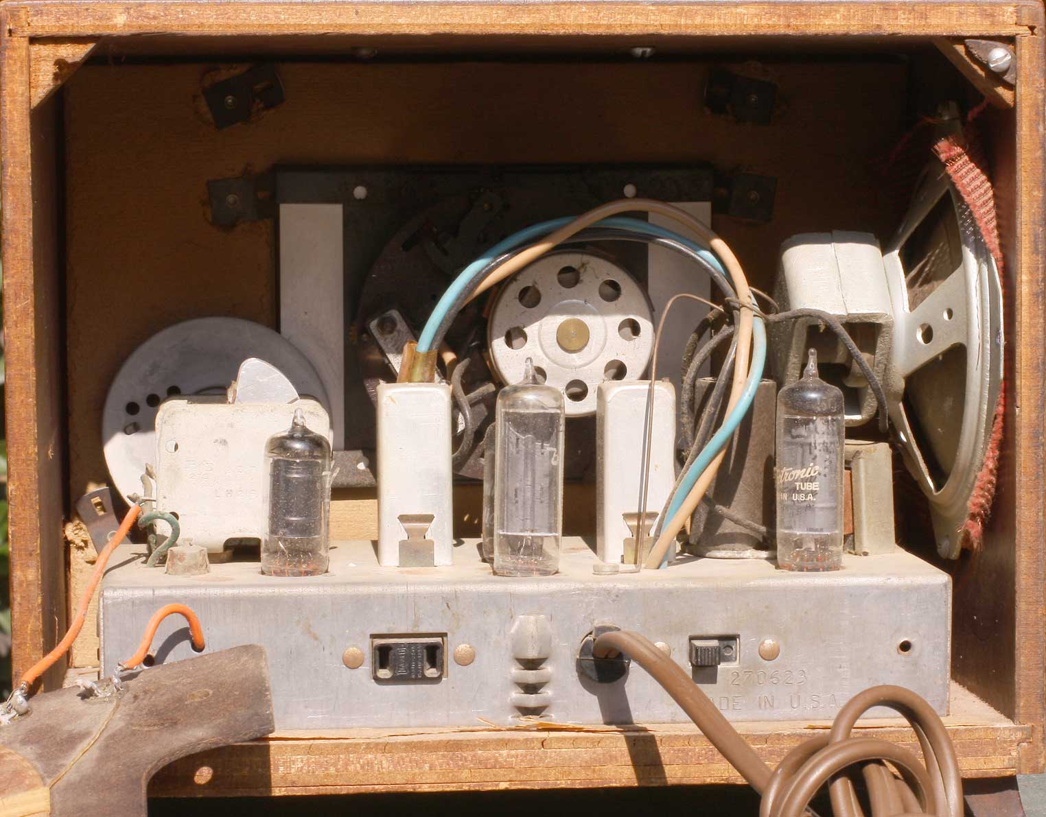
So now I've got the chassis out, with the speaker dangling—no big disasters. The dial cord and pointer is still intact (the pointer could use a little paint). It's dirty but everything appears to be there. Underneath it also appears intact. The caps are all old and waxy. I'm not impressed with the soldering job—some of it looks gunky and unprofessional—like something I would have done. So I think someone may have worked on this before.
Look it over, there's nothing obviously wrong. Everything appears to be connected. Let's see if it powers up. I have to jury rig something since removing the clock broke the circuit (the clock has to be able to turn the radio on and off), so I solder a jumper wire from here to there. Plug it in and—
BZZZZZTTT
—and a puff of smoke rolls out from under the chassis.
Oh—shoot. (not quite what I said). Unplugged it. Looked it over. I can't see what burned up. So—let's test the tubes.
 Now the next little debacle begins. As mentioned before, I use a friend's tester, a creaky Sylvaniar. It's too old to do all the tubes (in this case, the 50C5 output). If I spend the time, I may be able to figure out how the settings work so I can test tubes that aren't already on the list, but right now that's an avenue I don't want to take. So I test the others. The 12BE6 shows bad, the others are all good, but they're all failing the shorts test. [There's a rotary switch called SHORTS, and you spin it around to test for shorts across the various tube elements. If a lamp lights up, you supposedly have a short and your tube is no good.]
A phone call with The Old Man. Did I really blow out all my tubes? Probably not. My dad says he'll make up a set of AA5 tubes for me and mail them down. I'll have a known-good set and I can check the machine; and I can bring the old ones up with me next time and we'll test them on his Hickok tester.
That'll take about a week, so while I'm stalled I decided to re-cap the radio. The waxy old paper caps looked original, I wanted the practice, and I had a bunch of orange-drops already so why not. Doing that gave me some practice in unsoldering and resoldering, locating components in their physical locations vs. the schematic, verifying that things were connected up where they belonged, and degunked what turned out to be a lot of cold-solder joints (yuck). Since the orange drops are a lot smaller, that opened up some room and made it easier to trace connections and clean up.
The "new" tubes arrived. They all tested good on the Sylvania, but all showed as being shorted, so the tube tester's short test is unreliable. I went ahead and plugged all the new tubes in, including a new 50C5. I tested the 2-stage filter cap—it charged and didn't seem leaky, so okay. Fingers crossed. Let's fire it up again.
Expected more smoke, but instead I got AC hum. So at least I got power, and the power amp is good (and loud). Shut it off. I had a 3-stage filter cap in the junk box, so I tacked it in parallel to the old one and powered up again. Quiet this time, and I could hear stations. Hey hey! I've got a playing radio again.
Fast forward a week later, because I can only work on this thing in very small doses. Some of this is due to the work area problems that I'll discuss later. I disconnected the old filter can (thankfully it's only 2-stage) and soldered in the replacement. Everything looks okay. Fingers crossed. Plug it in and—it works, but something's wrong. I tuned into talk radio and it sounded like a robot, very clipped.
I finally figured out the problem. Got both the DMM and the VTVM fired up, and between the two I checked all the voltages as called out on the schematic, the ohm readings for all of the resistors, and checked that the big capactors were charging (the little ones are too fast). No unsoldered connections. No broken leads. No solder bridges to short things out. No more cold-solder joints from the previous owner.
Then when I was finally shutting everything down to add it to the heap of unfinished projects I'll have to take on the next trip to visit the Old Man, I accidentally knocked off the antenna connection, and for a split second thought that I heard clean audio before it went to white noise.
One of the things I had decided to do during disassembly was crimp push-plugs onto the antenna wires so I could push them on the loop antenna lugs, rather than solder the wires on directly. I still think this is worthwhile: the way it's constructed, you have to take the radio chassis, the clock, the speaker and the loop antenna out of the cabinet all at the same time, and it's a pain in the ass (particularly with the clock and speaker dangling only by their wires). It may have been easier to manufacture, but it would be a lot easier to work on if these sections all had plugs and I could just pull out the section I needed.
 I only did this with the antenna, but for whatever reason it just wreaked havoc. So I pulled the crimp-plugs off and soldered the wires directly onto the loop antenna lugs and behold—clean sound.
That was nearly it. I thought I had it, but something was going on and I wasn't getting much oomph on the amplification (sounded fine, but not loud). I had to take to see The Old Man anyway so I could dab some rosin on the dial cord so it would grip. Plugged it in and— nothing. Long story stort: I had the power wired up wrong again. So why did it work for me at home? Because I was still plugging it in by sticking a special AC cord into the appliance outlet, and that powered it fine. So we moved a wire, and whatever also fixed the sound problem.
Then—as I was putting it all back together for the final, at long last goddamn time—I broke the glass.
Antique Radio Forum has a thread from someone who broke his glass more severely—and fixed it.
Current status: this radio is no longer in my collection. This page will be removed in late 2024.