
Marconi
I don't care what anyone says about whom invented the radio. Marconi invented the radio. It's one thing to sit drawing rooms with slide rules and discuss ether waves over port and cigars; it's one thing to deliver scholoarly papers about them. Marconi actually put things together, got outside and put up antennas, and made it work.
It's easy to forget these days, but at the turn of the 20th century, wireless telegraphy (aka radio) was cutting edge technology; and like the very tip of cutting edge technologies, it worked—but it barely worked.
There were problems on both ends, but reception needed a lot of improvement to make radio useful. A receiver needs to do something called detection, which is how the information in a Radio Frequency (RF) wave is "detected" and turned into something humans understand.
The state of the art at the turn of the century was to use a coherer, which was a glass tube with metal (I believe iron) filings inside and an electrode on each end. The RF wave would set up a magnetic field that would cause the filings to align and touch each other, which created a conductive path. As the wave's magnetic field collapsed, so would the filings and the path would be broken. It was a neat idea but they had all kinds of problems, not the least of which is that they did not work for continuous-wave morse code or for AM; coherers just determined the presence or absence of signal.
Then there was the cat's whisker, also known as the crystal detector, which was an early semiconductor. You start with a crystal, usually Galena, and a little wire called a cat's whisker. The idea was to just barely touch the tip of the wire to the Galena, and that would form a one-way conductive path for the signal. Cats whiskers worked for CW and AM, and they had fewer problems than coherers. But they were notoriously finicky to set up, since the wire had to moved round to find the right spot on the crystal to touch, and finding the right spot was entirely trial-and-error; God help you if anything distrubed the connection because you'd have to do it all over again.
What they needed was a detector that only passed half of the incoming RF signal; either the positive phase or the negative phase, it didn't matter. But only half could be passed. This half would be pulsating DC. A capacitor would filter out the RF fluctuations, leaving only the bigger, Audio-Frequency pulse (AF). That AF pulse would drive a headphone or speaker.
The Edison Effect only passed one phase (the positive phase) of an alternating current wave.
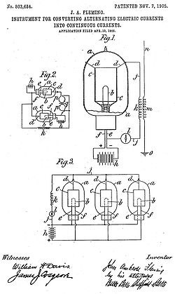
As Marconi set up his company and continued to refine and improve his equipment, he hired people to work on these things. One of them was John Ambrose Fleming, and electrical engineer who had worked with Edison during the light bulb years and was familiar with The Edison Effect. Fleming made a bulb with a filament, similar to a light bulb, and added another electrode, called a plate. By applying the incoming RF signal across the tube, only the positive half passed through. This worked like a check-valve, and the concept stuck. Fleming called his device an "oscillation valve." Most people now call it the Fleming valve. In the UK, all "tubes" are called valves.
The Fleming valve turned out to be a great detector. It wasn't finicky and fragile the way a cat's whisker was; it could handle CW and AM, unlike a coherer; and as it was developed and improved, it performed better than either. Its only real drawback was that it required power to run the filament, something coherers and cat's whiskers did not need.
Thermionic Emission
 Edison didn't know it at the time because the atomic model was still being developed. By the time Fleming was working on his valve, it was understood that what was going on was this: as the filament heated up, electrons boil off the outer edge and collect in a cloud around it. This is called a space charge, and it's got a negative charge. The size and intensity of the space charge varies with the heat of the filament, and also the material the filament is made of. Materials with loosely bound electrons will give them up easier at lower heat levels. But regardless, more heat equals more free electrons, equals bigger space charge. This is called thermionic emission: therm is heat, ionic is the negative space charge, and emission is the electrons boiling off the filament.
If you put a negative charge on the plate, nothing happens. If you put a positive charge on the plate, the electrons are attracted to it and you get a current flowing.
Diodes
I'm writing this at a time when the solid-state era has been around longer than the hollow-state era; when I heard the word "diode" I picture little silicon or germanium types, little beads impaled on a length of thin wire. But the word "diode" means a device with two electrodes, and these two-element tubes became "diodes."
In actual use, the term varies. Tubes used in power supplies are usually called "rectifiers," even though they're diodes. Tubes which use rectifying action for detection are usually called diodes.
Electrode Names
The filament is the source of electrons in these early tubes. The filament gets hot; electrons boil off into a space charge; a positively charged electrode draws them toward itself. The electrons enter the positively charged electrode and flow through the rest of the circuit.
In other areas of electronics, the source of the electrons is called the cathode and the receiver is called the anode. In tubes, the anode is called the plate. In early tubes, the plate was just that—a big flat target for the electrons to hit. Plates would soon evolve into a cylinder; the cathode is in the center so that electrons in the space charge surrounding the cathode would all have a direct path to the plate.
 As I said, in early tubes, the filament is the source of electrons. These are directly heated cathodes. In these cases, the cathode is called the filament. The schematic diagram just shows a filament and a plate. Later diodes added a seperate cathode as the source of electrons, and the filament is used simply as a source of heat. These tubes have indirectly heated cathodes, and the filament in these are called heaters. So a heater supplies heat to the cathode, which boils off electrons, which are attracted to the plate (or plates).
In a directly heated tube, the fluctuating A/C voltage varies the heat in the filament, which varies the space charge. In power supplies this isn't a problem, which is why directly-heated rectifiers are often used: the pulsating D/C output gets filtered using capacitors and a choke to provide steady D/C.
If you put a signal, like an radio-frequency (RF) or audio-frequency (AF) wave on it, the same thing happens. You get a pulsating D/C output. On early radios this worked fine because the filaments were heated with D/C current. So let's say you have a tube with a filament that runs on 5 volts DC as its base. Then you "impress" or apply a 1-volt A/C signal on to it; the filament voltage fluctuates between 4 and 6 volts. The 5 volt DC base (called a bias) is steady, so the fluctuation comes entirely from the A/C signal. If the frequency of the signal is 500 kHz going in, it's 500 kHz going out.
In the late 1920s, there was a big push to use household A/C to run radio sets. The problem is that household A/C (in the United States) has a frequency of 60 Hz, and it mixes with the RF or AF signal. If the 60 Hz frequency (called a beat) mixes with the RF or AF signal, it can be heard in the radio output; it's usually called A/C hum or 60-cycle hum.
Tube design engineers tried a variety of methods to deal with A/C hum problems; the method that won out was to add a seperate cathode. So the RF/AF signal went onto the cathode and the filament (now known as a heater) became the source of heat. A household A/C source on a filament still fluctuated, but not enough to affect the A/C signal on the cathode. So now they could use household A/C to provide power to all the tube filaments, without the 60-cycle hum.
Wave Rectification
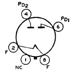 Power tubes used to convert A/C to D/C are called rectifiers. A typical rectifier has one cathode, which is the source of electrons, and one or two plates, which collect the electrons.
A diode with a single plate is called a half-wave rectifier; a diode with two plates is typically a full-wave rectifier. Early tubes often have one plate, but most later rectifiers have two, because you simply not connect the second plate if you don't want full-wave rectification.
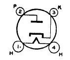
Single-plate diodes usually show up in pairs, called duo-diodes, where there are two separate cathodes and two plates, so you get two diodes in a single package, and each diode can be run independently. Tubes like these typically share a heater. A 6H6 is a good example.
That's about it for diodes. The next big leap in tube development is the Triode.
