
Eagle-eyed John Farmer was kind enough to drop me an email with a link to a Facebook Marketplace listing for this very set. Thank YOU. I've made some edits to my description below to incorporate the new info.
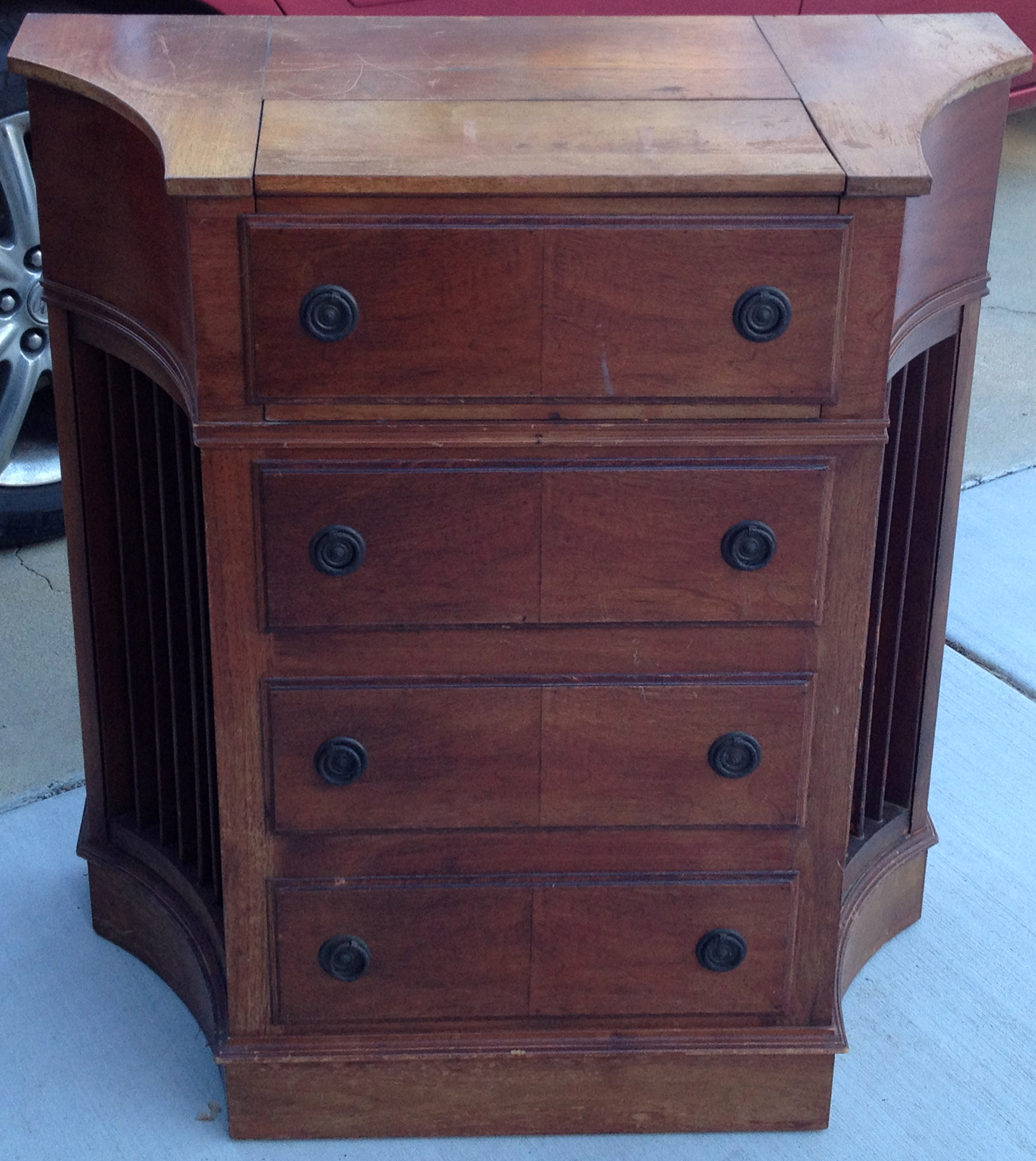
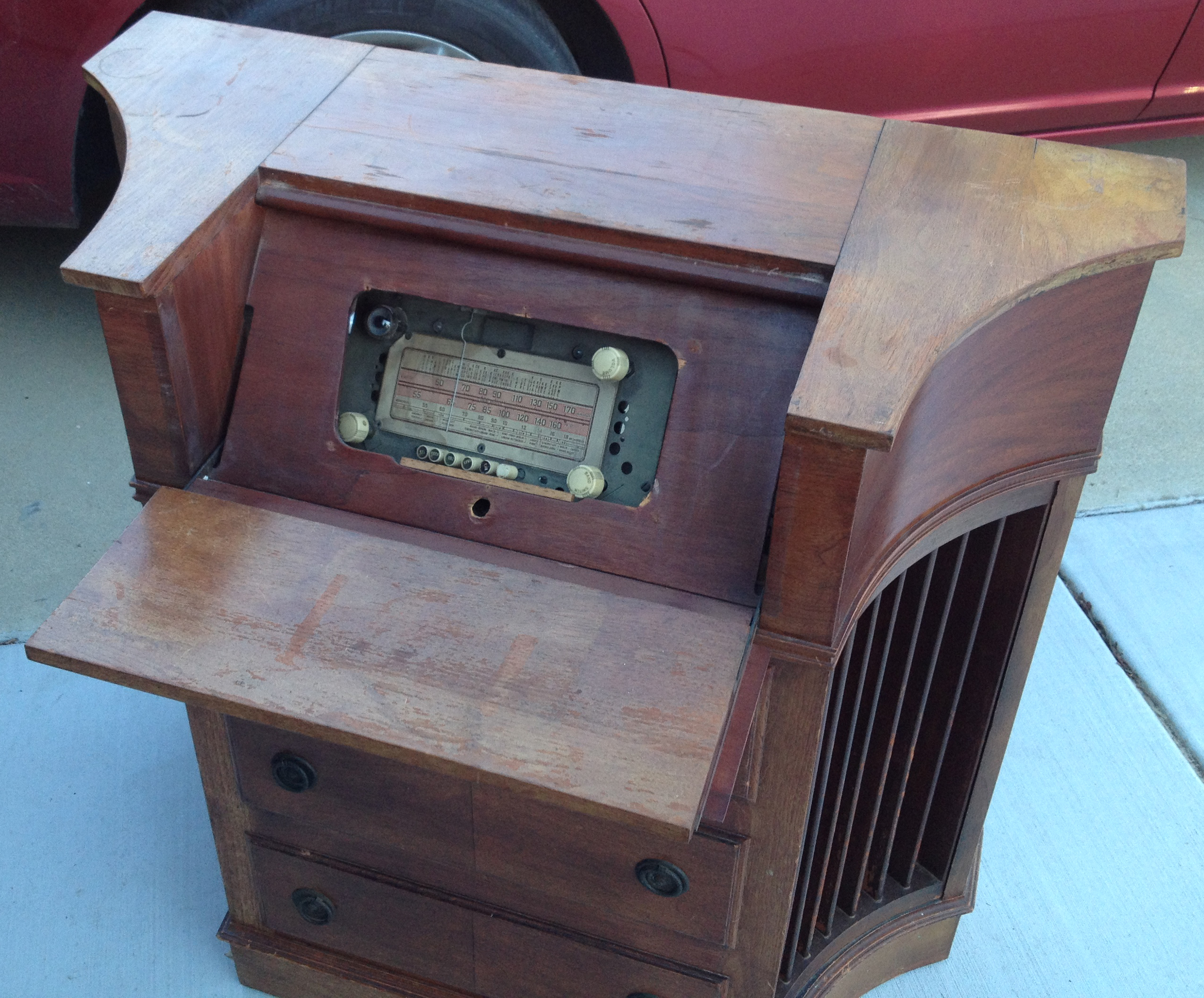
Another radio with no manufacturer's markings that I've been able to locate—neither on the cabinet nor on the chassis. It's missing the dial glass and a facia plate, which had the name. Or a decal or paper that was glued onto the cabinet disappeared over time.
More importantly, it's missing the escucheon, or face plate that goes over the dial and controls. That had the manufacturer's logo on it.
Tube compliment:
6A8G pentagrid converter
78 IF amplifier
75 2nd Detector / 1st audio
42 AF power amp
80 power supply
6E5 (6U5) magic eye for tuning
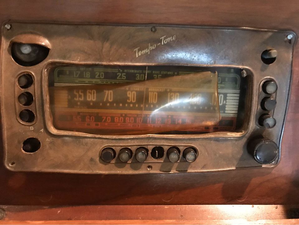
This turns out to be a Tempo-Tone, made by a Los Angeles-based company called Barker Brothers. There's very little info on Tempo-Tone on the internet, but there's a little about the maker. Barker Brothers was a big furniture manufacturer/retailer that ended up being something of a department store. They closed their locations in the 70s and 80s, but in their heyday before World War II, they were really something. J. H. Graham has a neat little write-up about them, and there are other artifacts on the internet.
The Missing Escucheon
 Obviously I don't have one. I was thinking that if I ever get a 3D printer and a simple CAD program, I'd try to make one. I figured I could probably design something close just by measuring where the holes ought to be, etc.
The set on Facebook made things a bit easier, since now I know what the original looked like. I also have a pretty good idea now what happened to mine. The one on the Facebook set has warped over time (plastics of that era do that. I've got a broken escucheon on my Silvertone 4786, which was also some kind of pre-WW2 plastic.
Chassis
I had a tough time pulling the chassis out. It's anchored into a platform by a couple of long screws that come up from underneath. One screw fell out on its own but the other held on. That second screw saved me some damage by keeping the chassis from falling out while the cabinet was being loaded and unloaded into my car, but worked against me later because I couldn't get it out at all. I'm not sure what happened except that I ended up cutting it off with an edge saw, and then I still had to drill the stub out of the bracket. What a pain.
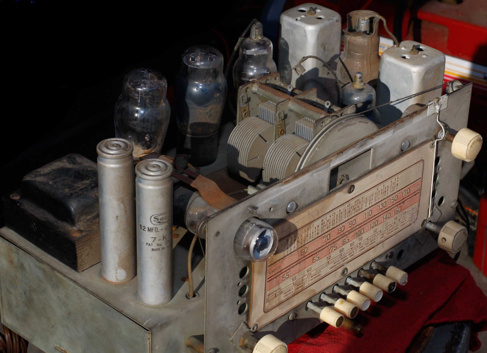

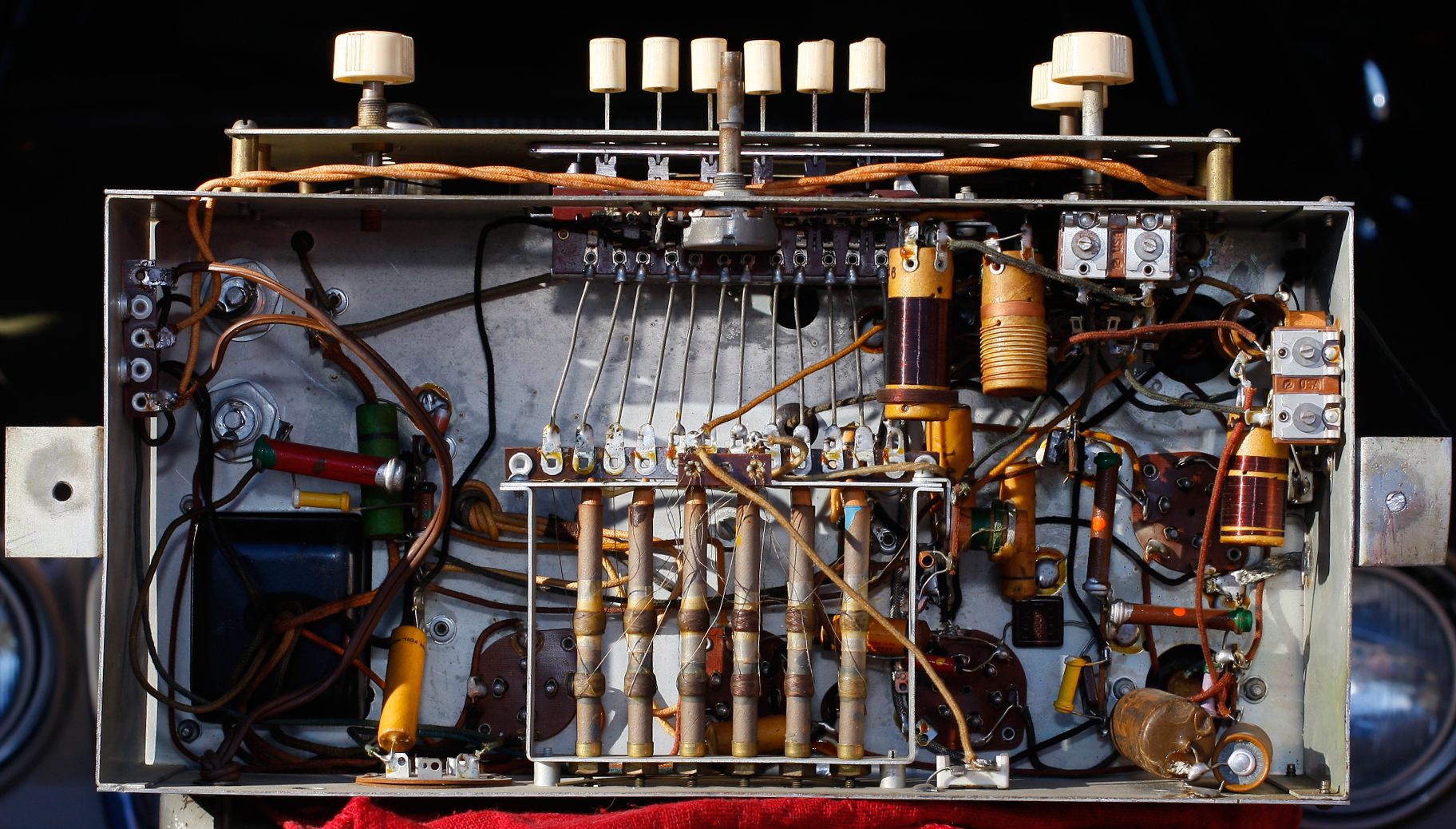

The chassis is filthy but looks largely untouched. All tubes tested good—even the pilot lamps lit. The dial cord is in place but shot, and will have to be replaced or tightened up.
I pulled the 80 rectifier, plugged the chassis into my variac at full line power and saw no signs of an internal short (high current draw), so I let it warm up a bit and replaced the 80. With high voltage on the amps, I got audio—a lot of audio. This sucker is loud. No stations but I got noise by touching the antenna wire ends (there are two wires that probably went to a loop antenna, or maybe binding posts on the back of the cabinet. There is no back on the cabinet, so I don't know what used to be there.
Also a lot of hum. I didn't want to take out those two big silo Solar electrolytics that look great on the top of the chassis, so I disconnected them underneath and tacked in two modern electrolytic equivalents instead. Still a huge hum. Found a third electrolytic on the other side of the chassis and replaced it. Still a huge amount of hum. So now it's a hunt.
No Schematic
The problem with department store radios, like Montgomery Wards (Airline) and Sears (Silvertone), did not publicly identify their suppliers on their house-brand equipment. Wards used to have a 3-digit prefix on a lot of their stuff, so if you knew the code you could tell the actual manufacturer. Barker Brothers's chassis has a 3-digit prefix and a longer number, and I assume it probably works the same way. But that does me little good.
Wards and Sears schematics, however, are available. So are Gamble-Skogmos, Wallgreens, Western Auto Supplys and others. Nostalgiair has a very few Barker Brothers schematics (courtesy the Riders PTM) but none of them are remotely like mine.
So I looked at my 3-volume Los Angeles Radio Manfucturing booklets and found a couple of mentions of Barker Brothers. They mentioned that Barker Brothers bought chassis from local manufacturers like Gilfillan, Troy, Packard-Bell, perhaps others. From the tubes and the features I figured this was probably made between 36 and 39, so I started leafing through schematics. Couldn't find anything even from those manufacturers that fit. I expanded my search for anything I could think of without success. I ran the tube compliment on Radiomuseum's search and only came up with a Douglas 311A from Brazil; I don't think so.
The thing is that the 6A8 never seemed to have a 78 as its IF transformer. 6A8s always seemed to have something else, almost always an octal tube, as an IF. All the 78 IFs I found nearly always had a 6A7 (or a non-RMA numbered tube) as a converter. What's the difference between a 6A7 and a 6A8?
Virtually nothing, it turns out. They're electrically identical and pin-compatible; the only difference is that the 6A8 has better internal capacitance figures. Could it be that my set originally had a 6A7, and the manufacturer updated to a 6A8 because it would work better on the upper bands? Or a service tech swapped it because he didn't have a 6A7 in stock?
Another search on Radiomuseum, this time with a 6A7. This time they included two American makers, Sparton and Wilcox-Gay. The Sparton turns out to be a monster with one of everything that GE made; but the Wilcox-Gay looks close. It's not right, but it's close.
But the Douglas is even closer. And anyway, I never found either of those until after the big work was done (below).
Back to Work
The Old Man, who worked on these things for a living, suggested the following (in order):
- Tack on another pair of filter electrolytics, just in case one or both of the new ones I put in are bad themselves (unlikely but an easy test)
- Swap the 80 rectifier tube
- Swap the 75 2nd Detector tube
- Go in with the o-scope and start looking for A/C where it shouldn't be
Went there, saw it, did it, bought the t-shirt. None of it worked. Checked all over hell trying to figure out where it was bleeding in and couldn't find it. I was going to visit my folks anyway, so I brought it with me and asked the Old Man to look at it.
The good part is that it took him more than 2 minutes to find it, so I wasn't completely embarassed. The bad part is that I likely would have never have figured it out on my own.
The problem turned out to be a ground strap located under one of the electrolytic capacitor lugs (the filter caps are bolted on, which makes them very easy to replace—provided you can find another one that's the same size). The strap serves as a convenient tie point for three or four items.
When I was replacing one of the filter caps, I was looking for a place to solder it to ground and considered that strap, but the meter said it wasn't really grounded to the chassis: there was a 1KΩ or so difference. I figured there must be an insulator under it and it meant to be above ground.
Did I mention that I couldn't find a schematic?
So after much probing and cursing and tests, sketching bits of diagram, looking at the "close" schematic and noting how far wrong it was, the Old Man finally figured out that the center tap from the power transformer's B winding was attached to that ground strap—the one that was was 1KΩ above ground. It should have been ground; there's oxydation or something that's corrupting the connection to the chassis. Ran a write over to a known ground and suddenly the hum went away: the center tap was feeding back into the power supply.
The downside was that I know I would never have figured that out. The upside was that this time I actually learned something.
Not So Rapid Radio Repair
After years (literally) of looking, I finally got a copy of Rapid Radio Repair by John Burke (not the ones by Charles Miller or Warren Heath). It just arrived and I saw there was a chapter on hum, so I went right to it and found this (page 48):
I should say that the greatest pitfall a serviceman can fall into is to listen to a set, hear a loud hum, jump to the conclusion that only filters are needed, and make an estimate on that basis. Even if curing the hum is relatively easy, the hum has prevented your hearing all sorts of other troubles the set had before it developed the hum.
Which turned out to be true. One of the problems with the radio was the on/off-volume pot. The switch portion was broken and a previous owner had fixed it by bypassing the switch entirely, so that on/off was now done by plugging and plugging at the wall. While I was frustrated chasing hum, one of the things I did as a break was to replace it with a new pot. And because I don't have a schematic, I was very careful to solder the wires back exactly as they'd been on the old pot.
That was a mistake. There were only two wires and, again after some gnashing of teeth and consulting "near" but incorrect schematic, the Old Man determined that they weren't doing anything clever—the top of the pot should have been grounded. Once that was fixed, the radio played decently. I hadn't noticed the original pot had a little wire that ran from the top pin to the metal casing, which would short it to chassis ground. So another lesson learned.
Stuffing Caps
Peaking the IF was pretty easy. I eventually figured out which caps to adjust to get the tracking and alignment on both bands. I even got one of the buttons tuned to a station, though the rest aren't doing it.
The next is to try to restuff the filter caps. These are interesting—I've never see them before: they screw in. There's only one stage in each, but it certaily makes them easy to handle.
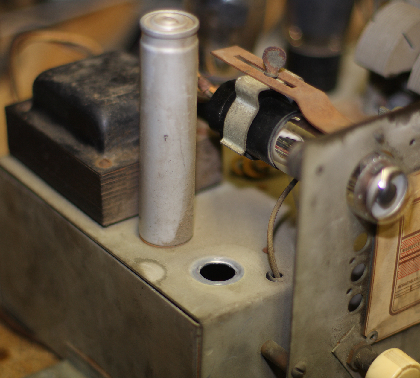 There are two: here's a photo of where they mount on the chassis; one is intact and the other I've removed. There's a big hex nut that holds it in place underneath.
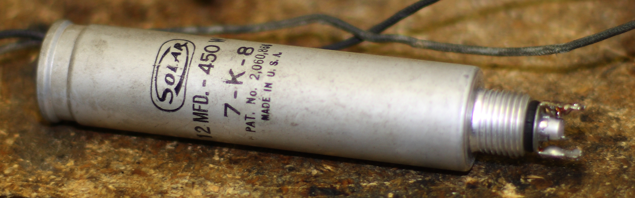
Here's the one that I pulled. You can see the screw-thread on the bottom. Leads solder onto the end.
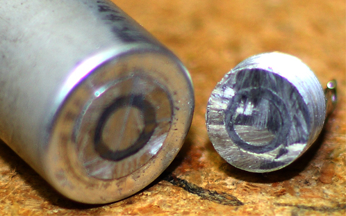
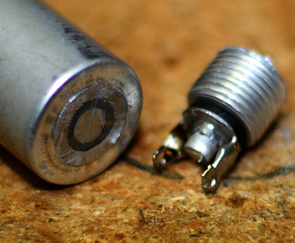 I sawed the end off with a coping saw.
So you can see it turns into three sections, with the separator being that dark circle in the center. The section inside the circle is insulated from the outside.
Once that was done, I put it back together, it plays. Put it back in the cabinet and it still plays. Can't ask too much more than that.
Current status: this radio is no longer in my collection. This page will be removed in late 2024.