
This is no longer in my collection; it is here for archival purposes only.
![]()
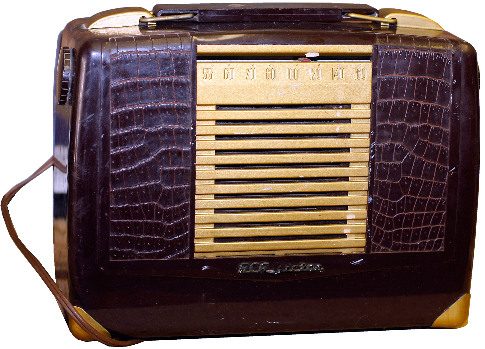
It's been awhile since I got a new project radio. This one was cheap; I liked the styling (even though it's beat up)—it's got a faux crocodile skin texture that's interesting; and I wanted something I thought I might actually be able to fix on my own.
This is a Rather Crappy Apparatus BX-57 from around 1950; it appears in Rider's Perpetual Troubleshooter Volume 20.
 Like a bunch of the radios on my miscellaneous projects page, this one is an AC/DC battery transformerless portable that runs off four 1v tubes: 1R5 converter, 1U4 IF amp, 1U5 2nd detector/AVC/1st AF, and a 3V4 final AF. What would have been the fifth tube was replaced by a selenium rectifier.
The Old Man didn't care too much for RCA: his complaint was that they went their own way and did strange things under the hood. That may be, but I thought their cosmetic designs were great. RCA made a lot of good looking radios, and they were a bit flashier. Zenith and Admiral, two other major companies I like, were quite a bit more conservative (Philco was fumpy).
Dead on arrival.
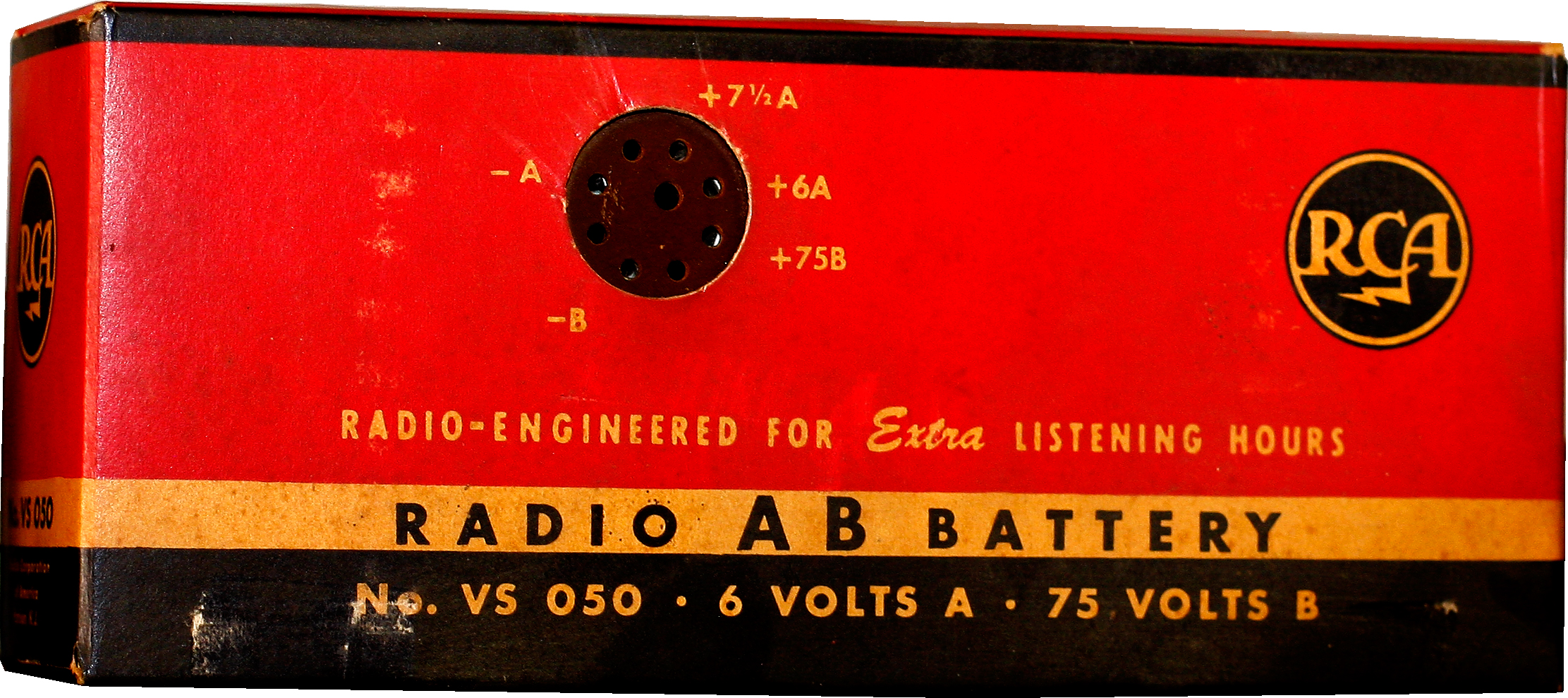
The case (plastic—I think it's vinyl, too flexible to be catalin) has some scars and road rash, but is still pretty-much intact. The pointer is still connected via the dial cord and moves. I opened it up and aside from an old spider's nest, it was clean and intact. I was particularly pleased to see a rarity—an original battery. And in nice condition, too. Too bad it's long, long dead.
 Once the battery was out, that left a lot of empty room in the cabinet but it's still difficult to maneuver, so I pulled the chassis. All tubes tested fine. Of course—if the trouble were just bad tubes it would be too easy.
The bottom of the chassis has a screwed-in plate and something was rattling around. Once took that off it was obvious what the rattle was: the shell of a big resistor, which turns out to be the 33Ω fuse resistor between the Se rectifier and the filter can. No great shakes since I figure I'll have to replace the rectifier with a modern Silicon (Seleniums go bad with age), which means I have to beef up the power resistor anyway because Si rectifiers have less resistance than Seleniums. And the filter can is likely dead too.
 That 33Ω resistor acted as a fuse (which may be why it broke), so if I'm smart I should probably try to insert a little in-line fuse in there somewhere.
Servicing by Following Smoke
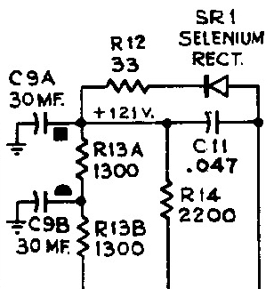
Turned out I was wrong about the broken resistor. It's broken all right, but it's not the fuse resistor. This big guy was wired in parallel across the rectfier and fuse to the filter cap. On the schematic (right), the fuse resistor is R12, and the big, broken resistor is where the C11 capacitor ought to be. Where is C11 in the actual radio? Not there.
I pulled the Se rectifier and put a beefy Si in its place, and added a 10Ω in-series between the diode and the fuse resistor, and put in a .047uF cap to conform with the schematic. Turn it on and bzzzzzt and a puff of smoke.
Looked it over and nothing looked burned up. I figured I'd shorted something and burned up all those 1V tubes, but they checked out okay. Huh. I checked the wiring and it looked okay. Turned it on again but this time chassis upside-down so I could watch it burn, and flipped it back off when I saw a trail of smoke appear at the end of the fuse resistor.
I haven't done anything since. Next up is I'll pull the fuse resistor, diode and cap, and I'll replace the resistors with a 47Ω 2W job I picked up, wire it back up and see if it burns again. I'm also going to run it through my fused pig-tail so it'll pop the fuse if it's pulling too much current. This is when I wish the power wattmeter on my Hickok Trace-o-Meter worked.
What We've Learned
Turns out there's a trick to this. You ready? The trick is you wire the new diode in using the proper polarity.
 So the radio came right to life, ancient capacitors and all. I'd replaced a few easy ones but left most alone. I was shocked that there was no AC hum. I got the bottom plate of the chassis back on without shorting anything, got the chassis back in the cabinet without discharging the filter cap with my fingers, tacked on the antenna wires. Reception! Tried aligning it but didn't get very far—the cabinet makes it difficult to get at the IF coils; there's an access hole for the LO and an antenna trimmer but they're still tough to get to, particularly the trimmer.
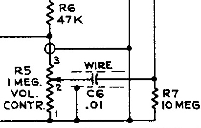
Here's something interesting that I've never seen before. There's a length of wire running from the volume pot to Pin 6 on the 1U5. The wire is wrapped several times around a paper capacitor and held with electrical tape. I thought it was some kind of bodge but no—it's on the schematic.
So there it is. Project complete.
Current status: no longer in my collection.